Electrical Installation
Safety First
| This manual is intended as a guide for proper installation. Invertek Drives Ltd cannot assume responsibility for the compliance or the non-compliance to any code, national, local or otherwise, for the proper installation of this drive or associated equipment. A hazard of personal injury and/or equipment damage exists if codes are ignored during installation. |
|---|---|
| This drive contains high voltage capacitors that take time to discharge after removal of the main supply. Before working on the drive, ensure isolation of the main supply from line inputs. Wait ten (10) minutes for the capacitors to discharge to safe voltage levels. Failure to observe this precaution could result in severe bodily injury or loss of life. |
| Only qualified electrical personnel familiar with the construction and operation of this equipment and the hazards involved should install, adjust, operate, or service this equipment. Read and understand this manual and other applicable manuals in their entirety before proceeding. Failure to observe this precaution could result in severe bodily injury or loss of life. |
Input Chokes
Supply | Drive Power Rating (kW) | AC Input Inductor |
|---|---|---|
230 Volt 1 Phase | 0.75 /1.5 / 2.2 | OPT-2-L1025-20 |
230 Volt 3 Phase | 4/5.5 /7.5 | OPT-2-L3036-20 |
11 | OPT-2-L3050-20 | |
15 / 18.5 / 22 | OPT-2-L3090-20 | |
30 / 37 | OPT-2-L3200-20 | |
400 Volt 3 Phase | 4 | OPT-2-L3010-20 |
5.5 /7.5/ 11 | OPT-2-L3036-20 | |
15 / 18.5 / 22 | OPT-2-L3050-20 | |
30 / 37 | OPT-2-L3090-20 |
|
Brake resistor Connections
The drive has an internal brake transistor fitted as standard and is enabled automatically when the regenerative energy from the load raises the drives internal DC bus to 390Vdc for the single and three phase 230V drives and 780Vdc for the 3 phase 400V drive.
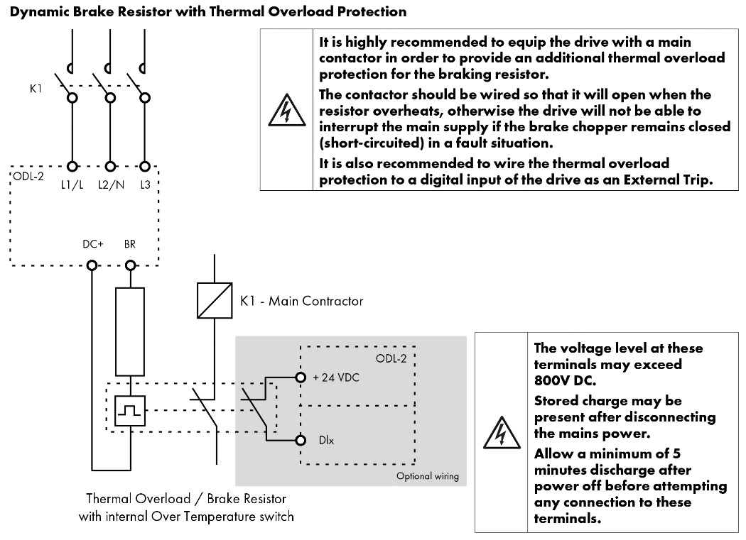
The brake resistor must be connected between the +DC and BR Terminals of the drive as shown in the images below, failure to do so can result in damage to the drive/Brake resistor.
 |
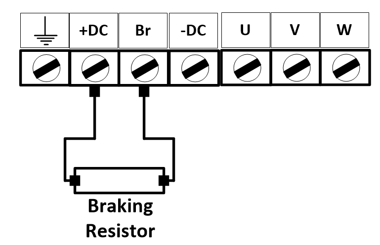 |
Brake resistor overload protection
 |
Providing the correct values have been entered into parameters P3-04 and P3-05 the drive will protect the brake resistor against overload.
For correct protection:
Enter the resistance of the brake resistor in P3-04 (Ohms)
Enter the power of the brake resistor in P3-05 (kW)
In addition to the drives in-built brake resistor overload protection
Control Terminal Wiring
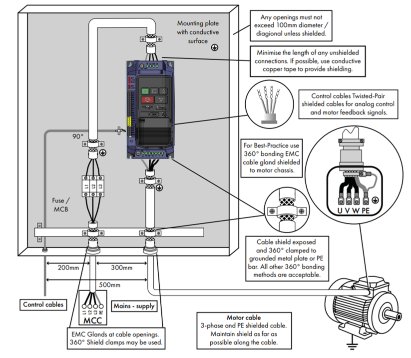
All analog signal cables should be suitably shielded. Twisted pair cables are recommended.
Power and Control Signal cables should be routed separately where possible, and must not be routed parallel to each other
Signal levels of different voltages e.g. 24 Volt DC and 110 Volt AC, should not be routed in the same cable.
Maximum control terminal tightening torque is 0.4Nm
See section 9.6 for further guidance on good EMC practices for control cabling.
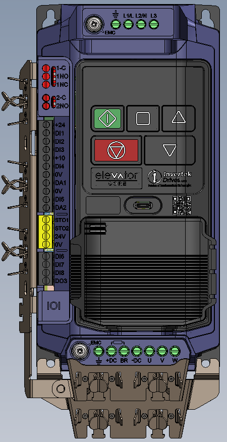
Control Terminals and ratings
Terminal Type | Terminal Rating | Terminal ID | |||
|---|---|---|---|---|---|
Relay Output 1 Common | Relay contacts, 8A/250VAC 10A/30VDC | 1-C | | ||
Relay Output 1 NO | Relay contacts, 8A/250VAC 10A/30VDC | 1NO | |||
Relay Output 1 NC | Relay contacts, 8A/250VAC 10A/30VDC | 1NC | |||
Relay Output 2 Common | Relay contacts, 6A/250VAC 6A/30VDC | 2-C | |||
Relay Output 2 NO | Relay contacts, 6A/250VAC 6A/30VDC | 2NO | |||
+ 24V User Input / Output | +24V from an external power supply / +24Vdc User Output* | +24 | |||
Digital Input 1 | Digital 8 – 30 Volt DC | DI 1 | |||
Digital Input 2 | Digital 8 – 30 Volt DC | DI 2 | |||
Digital Input 3 | Digital 8 – 30 Volt DC | DI 3 | |||
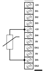
+ 10 Volt User Output | 10mA for user potentiometer | +10 | |||
Digital Input 4 / Analogue Input 1 | Digital 8 to 30V DC / Analogue 0-10, 0-20mA | DI 4 | |||
0 Volt Common | 0V | ||||
Output 1 | 1st Analog Output 0 to 10V, 4 to 20mA, /Digital 24V | DA1 | |||
0 Volt Common | 0V | ||||
Digital Input 5 /Analogue Input 2 | Digital 8 to 30V DC / Analogue 0-10, 0-20mA | DI 5 | |||
Output 2 | 2nd Analog Output 0 to 10V, 4 to 20mA, /Digital 24V | DA2 | |||
Drive hardware inhibit | +24 Volt (18 – 30 Volt) DC must be provided to enable power stage | STO1 STO2 | |||
+ 24V User Output | +24Vdc User Output* | 24V | |||
0 Volt Common | 0V | ||||
Digital Input 6 | Digital 8 – 30 Volt DC | DI 6 | |||
Digital Input 7 | Digital 8 – 30 Volt DC | DI 7 | |||
Digital Input 8 | Digital 8 – 30 Volt DC | DI 8 | |||
Digital Output 3 | Digital 8 – 30 Volt DC | DO3 | |||
*200mA maximum output current capacity in total for both +24V user outputs
Positive and Negative Logic
By default, the drive operates in positive logic, P1-43 allows negative logic to be set (Not STO1 and STO2 inputs)
Control Terminal Configuration.
P1-02 defines the function of each of the control terminals and should be set to match the connected controller, see section 15.5.2 Control Terminal Function Select.
EMC Compliant Installation
Installation within the UK and European Union
All equipment installed within the UK or European Union must comply with the applicable UK or European EMC Directive. The installer must be familiar with the Directive and appropriate good EMC practice. Invertek Drives’ products may be considered as a Basic Drive Module or Complete Drive Module according to the EMC standard definition dependent on the drive type. The BDM or CDM may then be incorporated into a Power Drive System. It is the sole responsibility of the installer to ensure that the complete PDS is compliant with the Directive.
This section of the User Guide provides general guidance to ensure compliance can be achieved.
| An optional Cable support bracket is available to allow easy termination of cable shields/screens. Size 2 shown below.
Part Number :
|
Grounding the Drive
Grounding Guidelines
Adequate safety earthing must be provided in accordance with local wiring rules and codes of practice. The ground terminal of the drive should be connected back to the common safety earth bar to maintain touch potentials within safe limits.
The ground terminal the drive should be individually connected DIRECTLY to the site ground bus bar (through the EMC filter if installed).
Drive ground connections should not loop from one drive to another, or to, or from any other equipment. Ground impedance must conform to local industrial safety regulations and/or electrical codes.
To meet UL regulations, UL approved ring crimp terminals should be used for all ground wiring connections.
The integrity of all ground connections should be checked periodically.
Protective Earth Conductor
The Cross-sectional area of the PE Conductor must be at least equal to that of the incoming supply conductor.
Motor Ground
The motor ground must be connected to one of the ground terminals on the drive.
Ground Fault Monitoring
As with all inverters, a leakage current to earth can exist. The drive is designed to produce the minimum possible leakage current whilst complying with worldwide standards. The level of current is affected by motor cable length and type, the effective switching frequency, the earth connections used and the type of RFI filter installed. If an ELCB (Earth Leakage Circuit Breaker) is to be used, the following conditions apply:
A Type B Device must be used.
A device with 10ms trip delay is recommended.
Individual device should be used for each drive.
The device must be suitable for protecting equipment with a DC component in the leakage current.
The device should be not sensitive to high frequency leakage current.
Shield Termination (Cable Screen)
The safety ground terminal provides a grounding point for the motor cable shield. The motor cable shield connected to this terminal (drive end) should also be connected to the motor frame (motor end). Use a shield terminating, EMI clamp or optional EMC bracket to connect the shield to the safety ground terminal, refer to section 9.6 EMC Compliant Installation.

