Rescue Operation
Rescue operation is normally used in the event of a mains borne power failure, with the primary goal of moving the elevator car at a limited motor speed for passenger evacuation, the power source comes from either DC (Batteries) or a UPS power supply as defined by the setting of P7-01 and with wiring in accordance with the connection diagrams shown below.
Par | Parameter Name | Minimum | Maximum | Default | Units | Visibility Modes | Accessibility | |
|---|---|---|---|---|---|---|---|---|
P7-01 | Rescue Supply Type | 0 | 2 | 0 | - | |||
Select what type of power supply is being used for Rescue Mode Operation | ||||||||
Setting | Power Supply | |||||||
UPS230 | 230VAC 1ph UPS | |||||||
UPS400 | 400VAC 2ph UPS | |||||||
bAtt | Battery Operation |
Rescue operation with a UPS
UPS power supply requirements
Nominal Rating | Minimum Voltage | Maximum Voltage | VA Rating | ||||||
|---|---|---|---|---|---|---|---|---|---|
230VAC 1Ph | 160VAC (226Vdc) | 280VAC | >= 230 x Motor Rated Current P4-03 Typical UPS ratings
|
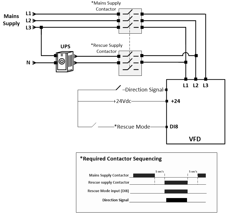
UPS power supply connection method
| *Required Contactor Sequencing
Note : Circuit protection must be provided. |
|---|
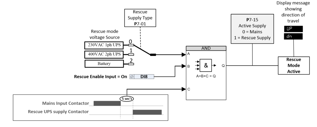
Activating UPS Rescue mode
| The drive will only run when a direction command is given. Direction of travel can be shown on the display by pressing the |
|---|
Rescue operation with Batteries
Battery supply requirements
Supply | Minimum Voltage Range | Nominal Battery Voltage | Maximum Battery Voltage | Current requirement |
|---|---|---|---|---|
Main Voltage Input (+/-DC terminals) | 32Vdc (<24Vdc will result in an undervoltage trip) | 48Vdc | Rated DC voltage | Motor Rated current (P4-03) and considering overload, typically no greater than 200% |
Control Voltage Input (+24V terminals) | 20V | 24V | 26V | 2.2A (60W) |
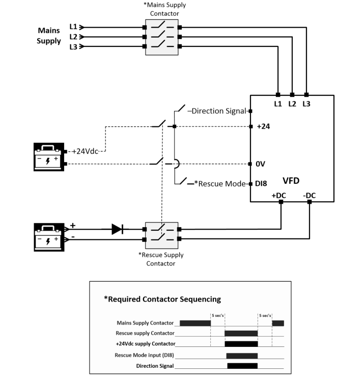
Battery power supply connection method
| *Required Contactor Sequencing
Note : Circuit protection must be provided. |
|---|
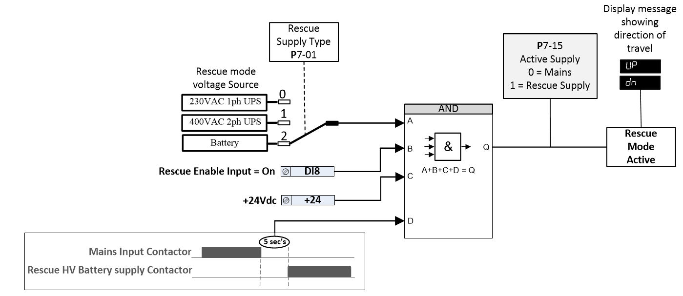
Activating Battery Rescue mode
| The drive will only run when a direction command is given. Direction of travel can be shown on the display by pressing the |
|---|
Par | Parameter Name | Minimum | Maximum | Default | Units | Visibility Modes | Accessibility | |||||||||
|---|---|---|---|---|---|---|---|---|---|---|---|---|---|---|---|---|
P7-02 | Rescue Operation Mode | 0 | 3 | 0 | - | |||||||||||
There are 3 types of rescue mode operation, the following points of consideration help select the most suitable mode:
| ||||||||||||||||
0 | Basic Rescue Mode | |||||||||||||||
When Rescue mode is enabled the travel Direction is governed by the direction command given to the drive from the controller, the travel Speed is defined by the rescue mode speed parameter P7-03. Limited by UPS limit value set in parameter P7-04. | ||||||||||||||||
1 | Light Load Detection | |||||||||||||||
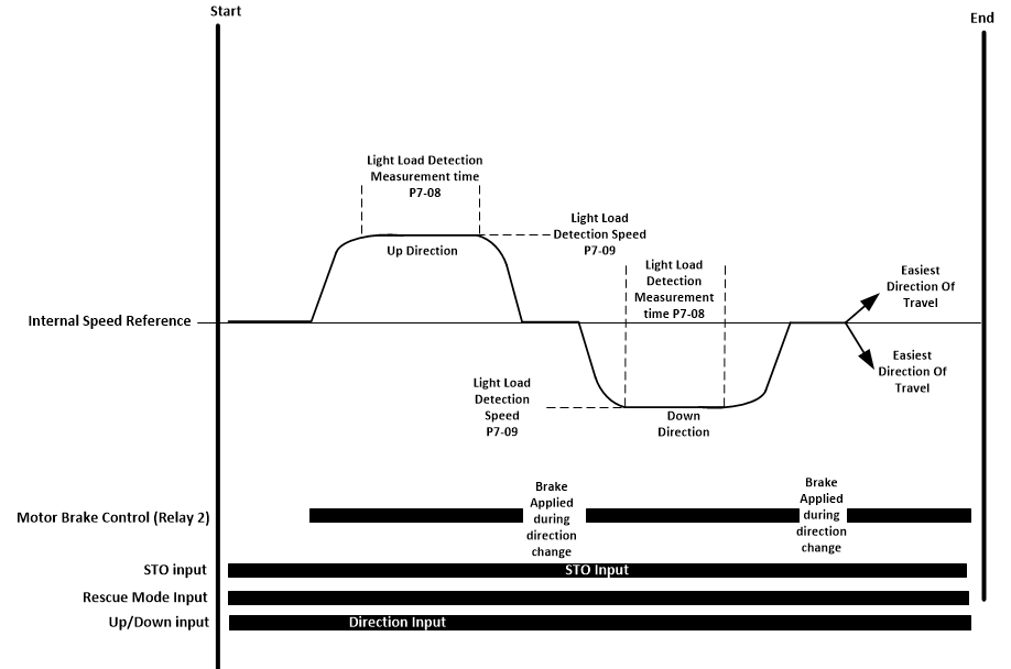
In this Mode the drive runs the motor in both directions (upward first) at a limited speed (P7-09) and limited time (P7-08) to measure which travel direction is the easiest as illustrated in the diagram below:
Note : Upward direction (motor clockwise with sheave facing you). | ||||||||||||||||
2 | UPS Easiest Direction based on Load Measurement | |||||||||||||||
In this Mode the drive measures and stores the load during each brake release, this value is then used to determine the easiest direction when rescue mode is next activated.
| ||||||||||||||||
3 | Reserved | |||||||||||||||
P7-03 | Rescue Mode Speed | 0.0 | P8-01 | 5.0Hz | Hz/rpm/Linear | All | R/W | |||||||||
This parameter defines the motor speed during rescue mode operation (when Rescue mode Input is activated), the value is also controlled internally by the power limit function based on the UPS rating entered into parameter P7-04. The actual achievable speed will be limited depending on a number of factors such as DC bus voltage level, motor, travel speed, system efficiencies, estimated value can be calculated as follows : Rescue Mode Speed Limit = DC Bus Voltage (P0-47) x Motor Rated Frequency (P4-04) 1.7 X Motor Rated Voltage (P4-02) It should also be noted that the level of motor load will affect the available DC bus Voltage; in some cases it may be necessary to reduce the Rescue Speed further in order to prevent nuisance Under Voltage (“”) trips. Vs P7-04? what about battery ? | ||||||||||||||||
P7-04 | UPS Rating | 0.0 | 100.00 | Drive Rated power/8 | kW | All | R/W | |||||||||
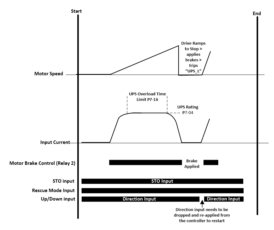
Used to protect overloading/ collapsing of voltage of the UPS power supply which could cause a motor stall condition. When the output power to the motor exceeds this value for the time set in parameter (P7-16) UPS Overload Time Limit, the drive will ramp down to Stop, apply brakes (if controlled by the drive) and trip on “UPS-L”, to restart a new direction command will need to be provided by the controller. If value is set to 0.0 then this function is disabled.
| ||||||||||||||||
P7-05 | Rescue Mode Current Limit | 0.0 | 200.0 | 100.0 | % | All | R/W | |||||||||
Set the current limit during rescue mode operation. | ||||||||||||||||
P7-06 | Rescue Mode Proportional Speed Loop Gain | 0.0 | 400 | 10.0 | % | All | R/W | |||||||||
P7-07 | Rescue Mode Integral Speed Loop Gain | 0 | 1000 | 50 | ms | All | R/W | |||||||||
Rescue mode Gains improve speed stability during rescue operation. |
Par | Parameter Name | Minimum | Maximum | Default | Units | Visibility Modes | Accessibility | ||||||
|---|---|---|---|---|---|---|---|---|---|---|---|---|---|
P7-08 | Light Load Detection Measurement time | 0.0 | 10.0 | 1.0 | s | All | R/W | ||||||
This parameter determines the time in which the light load detection function runs at the speed set in P7-10 (Light Load Speed Detection Speed) in each direction. | |||||||||||||
P7-09 | Light Load Detection Speed | 0.00 | P8-01 | 5.00Hz | Hz/rpm/Linear | All | R/W | ||||||
This parameter determines the motor speed in which the light load detection function runs at. | |||||||||||||
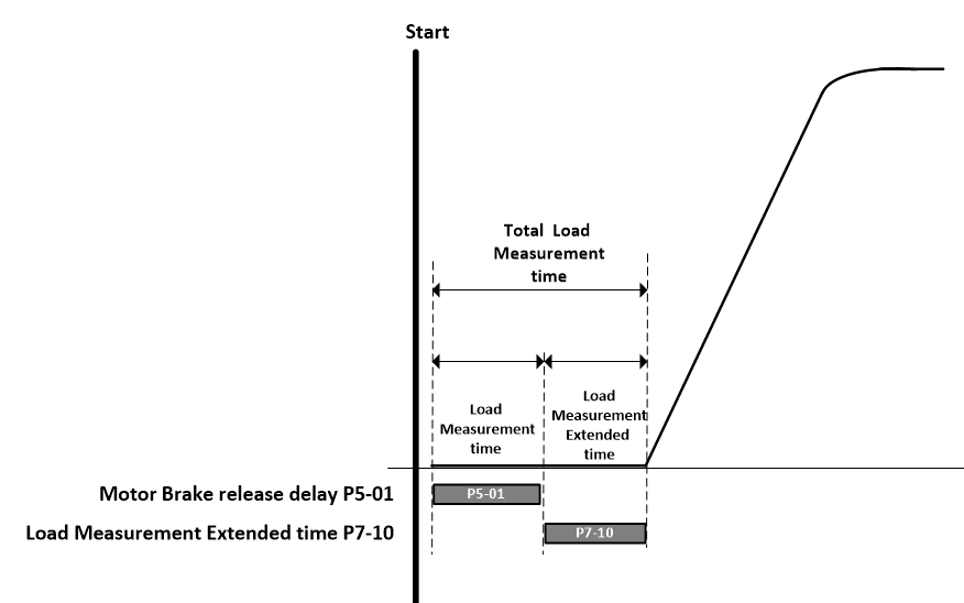
P7-10 | Load Measurement extended time | 0.0 | 10.0 | 0.0 | s | All | R/W | ||||||
Increasing this value can help improve the measurement accuracy of the light load detection feature. | |||||||||||||
P7-11 | Light Load Detection Result | 0 | 2 | 0 | - | All | RO | ||||||
This parameter shows the result of the light load detection function test. P7-02=1 and P7-02 =2 0 = Light direction is clockwise 1 = Light direction is Anti-clockwise 2 = Balanced | |||||||||||||
P7-12 | Energy Saving Rescue Unbalancing Maximum Speed | 0.00 | TBC | 5.00 | Hz/rpm/Linear | All | R/W | ||||||
P7-13 | Energy Saving Rescue Minimum Speed | 0.00 | TBC | 5.00 | Hz/rpm/Linear | All | R/W | ||||||
P7-14 | Energy Saving Rescue Minimum Speed time | 0.0 | TBC | 0.0 | s | All | R/W | ||||||
P7-15 | Active Supply | 0 | 1 | 0 | - | All | RO | ||||||
Displays the active supply that the drive is being operated from. 0 = Mains Supply 1 = Rescue Supply | |||||||||||||
P7-16 | UPS Overload Time Limit | 0 | 10.0 | 2.0 | s | All | R/W | ||||||
Used in conjunction with parameter P7-04 (UPS rating) |
Rescue Operation indicators
When the drive is operating in rescue operation the drive can indicate that rescue operation is active using the following methods:
Keypad display will show direction of travel “Up" or "Dn”.
Read Only parameter P7-15 (Active Supply) will show that rescue mode is active
Any of the digital or relay outputs set as function 9 can be used to indicate when Rescue Mode is active.
Any of the digital or relay outputs set as function 17 can be used to indicate the result of the light load detection measurement.
Functions disabled/Different in Rescue Operation
When the drive is operating in rescue mode the following functions will automatically be disabled/modified.
Input Phase Loss detection is disabled.
DC bus Ripple detection is disabled.
Reduced Undervoltage trip levels in accordance with the voltage supply Range as detailed in section 15.11.1.1 and 15.11.2.1.
S- Ramps/Jerks are not used during travel.
Motor brake control operates as per normal mains borne supply operation.
Dedicated speed loop gains (P7-06 Rescue Mode P-Gain and P7-07 Rescue Mode I-Gain) will be available as generally the gain is much lower to allow for a softer start for less of a surge on the UPS/Battery output.
Motor Auto-tune or Encoder offset (P4-08>0) are not permitted when operating in Rescue Operation
