Safe Torque Off
Note
The Safe Torque Off (STO) input provides the drive hardware enable function. Drives are supplied with the STO terminals linked as shown below.
To use the STO safety function and achieve the specified safety rating, remove the factory-fitted links and connect the STO inputs to a suitable safety relay or safety controller.
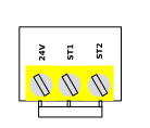
Safe Torque OFF will be referred to as STO through the remainder of this section. If the STO function is not required, the STO inputs must remain linked between terminal 24V and terminals ST1 and ST2. Drives are supplied from the factory with these links fitted.
Please read the remainder of this chapter for further information about the functionality and limitations of the STO circuit.
Safety function and safe state
The safe torque off (STO) function of the drive is implemented only by hardware and no software is involved to perform the STO function.
The STO function is available for the operator to turn off the motor torque. It is intended to be used in safety related applications up to SIL 3 acc. to EN 61800-5-2, EN 61508 and EN 62061, and up to Cat. 4 / PL e acc. to EN ISO 13849-1.
Safety function
The power that can cause rotation (or motion in the case of a linear motor) shall be switched off from the motor when demanded.
Safe state
The safe state is achieved when torque-producing power is removed from the motor.
Responsibilities
The machine or system designer is responsible for :
Performing a risk assessment of the complete machine.
Ensuring the required safety performance level or SIL is achieved.
Verifying correct implementation of the safety system.
Confirming correct STO operation prior to commissioning.
The system designer shall determine the possible risks and hazards within the system by carrying out a thorough risk and hazard analysis, the outcome of the analysis should provide an estimate of the possible hazards, furthermore, determine the risk levels and identify any needs for risk reduction. The STO function should be evaluated to ensure it can sufficiently meet the risk level required.
What STO Provides
The STO function prevents the drive from generating motor torque whenever either STO input channel (ST1 or ST2) is de-energised., this allows the drive to be incorporated into a complete safety control system where STO requirements need to be fulfilled.
The STO function can typically eliminate the need for electro-mechanical contactors with cross-checking auxiliary contacts as per normally required to provide safety functions.
The drive has the STO function built-in as standard and complies with the definition of “Safe torque off“ as defined by IEC 61800-5- 2:2016. The STO function results in an uncontrolled stop (Stop Category 0) in accordance with IEC 60204-1. This means that the motor will coast to a stop when the STO function is activated, this method of stopping should be confirmed as being acceptable to the system the motor is driving. The STO function is recognised as a fail-safe method even in the case where the STO signal is absent and a single fault within the drive has occurred, the drive has been proven in respect of this by meeting the following safety standards.
Standard | Result | Certification body |
|---|---|---|
EN 61800-5-2:2017, EN 61508:2010 and EN 62061:2021+A1:2024 | SIL 3 | Certified by UL |
EN ISO 13849-1:2023 | Performance Level (PL) = e, Category 4 | |
EN 60204-1:2018+A1:2025 | Uncontrolled Stop “Category 0” | |
Probability of Dangerous Failure per Hour | PFHD <10-8 | |
Safety element type | Type A (Route 1h) | |
Safe failure fraction | >90% | |
Hardware Fault Tolerance | 1 | |
Diagnostic Coverage (DC) | >90% | |
HFT architecture | 1oo2 Sensor & final element | |
Response time | <20ms | |
PLC test pulse immunity | <1ms per second |
Note
The STO safety certification applies only to drives carrying the UL marking on the product rating label.
The values achieved above maybe jeopardised if the drive is installed outside of the Environmental limits detailed in Section 3.2 and 6.3.
What "STO" Does Not Provide
Caution
Disconnect and ISOLATE the drive before attempting any work on it. The STO function does not prevent high voltages from being present at the drive power terminals.
The STO function does not prevent an automatic or unexpected restart when the STO inputs are re-energised. As soon as the STO inputs receive the relevant signal it is possible (subject to parameter settings) to restart automatically, based on this, the function should not be used for carrying out short-term non-electrical machinery operations (such as cleaning or maintenance work).
In some applications additional measures may be required to fulfill the systems safety function needs: the STO function does not provide motor braking. In the case where motor braking is required a time delay safety relay and/or a mechanical brake arrangement or similar method should be adopted, consideration should be made over the required safety function when braking as the drive braking circuit alone cannot be relied upon as a fail-safe method.
When using Permanent Magnet motors and in the unlikely event of a multiple output power devices failing then the motor shaft may rotate by up to 180/p mechanical degrees, where p is the number of motor pole pairs.
"STO" Operation
When the STO inputs are energised, the STO function is in a standby state, if the drive is then given a “Start signal/command” (as per the start source method selected in P-12.0) then the drive will start and operate normally.
When the STO inputs are de-energised then the STO Function is activated and stops the drive (Motor will coast), the drive is now in “Safe Torque Off” mode.
To exit STO mode, any active faults must be reset and both STO inputs re-energised.
The STO inputs are positive logic inputs only and are therefore not affected by the setting of parameter P-39 (Positive/negative logic select).
Inputs ST1 and ST2 must switch within 100 ms of each other; otherwise the drive trips Sto-F, requiring a power cycle to reset.
STO Status and Monitoring
There are several methods for monitoring the status of the STO input, these are detailed below:
Drive Display
In normal drive operation (Mains AC power), when the drives STO input is de-energised (STO Function activated) the drive will highlight this by displaying "InHIbIt".
NOTE: If the drive is in a tripped condition then the relevant trip will be displayed and not “InHIbIt”).
Drive Status parameter
Parameter P0-03 can be viewed to see the STO input status as illustrated below :
P0-03 Value | ST1/ST2 Input State |
|---|---|
0 | Open |
1 | Closed |
Drive Output Relay and Digital Outputs
Relay 1 or the digital outputs can be used to monitor the status of the STO inputs by setting the function to 15.
For Relay 1 set P-18 to 15
For Digital Output 1 (DA1) set P-25.0 to 0 and P-25.1 to 15
STO Fault Codes
Display message | No. | Description | Corrective Action/Further information |
Sto-F | 29 | Internal STO circuit Error / Channel interlock timing exceeded | Check supply to terminals ST1 and ST2 is >18V. |
Sto-L | 101 | ST1 / ST2 inputs opened whilst drive running | If ST1/ST2 has activated when this is not expected for the application, investigate the reason for the activation and rectify any faults before resuming operation. |
STO Function Response Time
The total response time is the time from a safety related event occurring to the components (sum of) within the system responding and becoming safe. (Stop Category 0 in accordance with IEC 60204-1)
The response time from the STO inputs being de-energised to the output of the drive being in a state that will not produce torque in the motor (STO active) is less than 20ms.
The response time from the STO inputs being de-energised to the STO monitoring status changing state is less than 20ms.
The response time from the drive sensing a fault in the STO circuit to the drive displaying the fault on the display/digital output showing drive not healthy is less than 20ms.
STO Electrical Installation
Caution
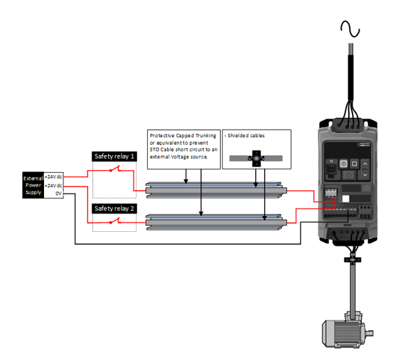
The STO wiring shall be protected from inadvertent short circuits or tampering which could lead to failure of the STO input signal, further guidance is given in the diagrams below.
In addition to the wiring guidelines for the STO circuit below, the Section "EMC compliant installation" should also be followed.
The drive should be wired as illustrated below; the 24Vdc signal source applied to the “ST1 and ST2” inputs can be either from the 24Vdc on the drive or from an External 24Vdc power supply (as per the diagram below), noting that the same installation rules apply for protection of the cables.
The diagram below only considers the STO part of the circuit for a full system wiring diagram then refer to Section 7.3.
Recommended STO Wiring
Note
The maximum cable length from voltage source to the drive terminals should not exceed 25 meters.
Dangerous failure modes
A short circuit in the wiring between the switch and the ST1/ST2 terminals can lead to a hazardous condition.
To minimize this risk, a safety relay with wiring diagnostics or a wiring method that reduces short-circuit hazards, such as shielded grounding or channel separation, is recommended.
Installation, Commissioning and maintenance instructions
STO provides an uncontrolled stop (Stop Category 0).
STO does not prevent automatic restart after re-energisation.
STO does not provide motor braking.
Additional protective measures may be required depending on the application.
The machine designer is responsible for ensuring the required safety integrity and correct system implementation.
Setup and Operation of the STO
Start-Up Condition: This test checks that the STO outputs are not enabled automatically upon application of power when the STO inputs are not present.
STO Interlock – Drive Output Idle: This test checks that, when the drive is idle, removal of one or both STO inputs results in torque being removed from the motor and that the control signals cannot override this state. The STO state is also verified to be correctly reported to the user via the keypad.
The test is summarised as follows:
With the drive switched on both STO inputs are applied.
Drive verified to transition into STOP state, and correctly reported on the keypad.
ST1 input is removed by opening the associated switch.
Drive verified to transition into INHIBIT state, and correctly reported on the keypad.
ST2 input is toggled in this state and is observed to have no effect on the INHIBIT state.
ST1 input is returned, and drive verified to transition back to STOP state.
The test is then repeated for the STO2 channel.
STO Interlock – Drive Output Active: This test checks that, when the drive is running a motor, removal of one or both STO inputs results in torque being removed from the motor and that the control signals cannot override this state. The STO state is also verified to be correctly reported to the user via the user display.
The test is summarised as follows:
With the drive switched on both STO inputs are applied.
Drive verified to transition into STOP state, and correctly reported on the keypad.
Give a start command (as per the primary command source selected in P-12.0)
Drive verified to transition into motor running state, with output details reported on the keypad.
ST1 input is removed by opening the associated switch.
Drive verified to transition into INHIBIT state with an STO-L trip (STO opened while drive is running), and correctly reported on the remote keypad and LED indications.
ST2 input is toggled in this state and is observed to have no effect on the INHIBIT state.
ST1 input is returned, and drive verified to transition back to motor running state.
The test is then repeated for the ST2 channel.
External Power Supply Specification
Voltage Rating (Nominal) | 24Vdc |
STO Logic High | 18-30Vdc (Safe torque off in standby) |
Current Consumption (Maximum) | 100mA |
Safety Relay Specification
The safety relay should be chosen so that at minimum it meets the safety standards in which the drive meets.
Standard Requirements | SIL3 or PLe or better (With Forcibly guided Contacts) **UL** |
Number of Output Contacts | 2 independent |
Switching Voltage Rating | 30Vdc |
Switching Current | 100mA |
STO Function Maintenance.
The STO safety function incorporates an integrated self-testing and diagnostic circuit which continuously monitors the internal safety path during operation. No periodic manual testing or maintenance is required under normal operating conditions. If a fault is detected, the drive will prevent operation and indicate the fault condition
Requirements of Proof Test
This device shall be subjected to a proof test at least once every 10 years. Please contact the factory or your local Sales representative.
Revision History
Important
Any changes to this Safe Torque Off document must be logged in the revision history table below.
Revision No | Date | Change |
|---|---|---|
1.0 | 25/08/2026 | Initial Creation |