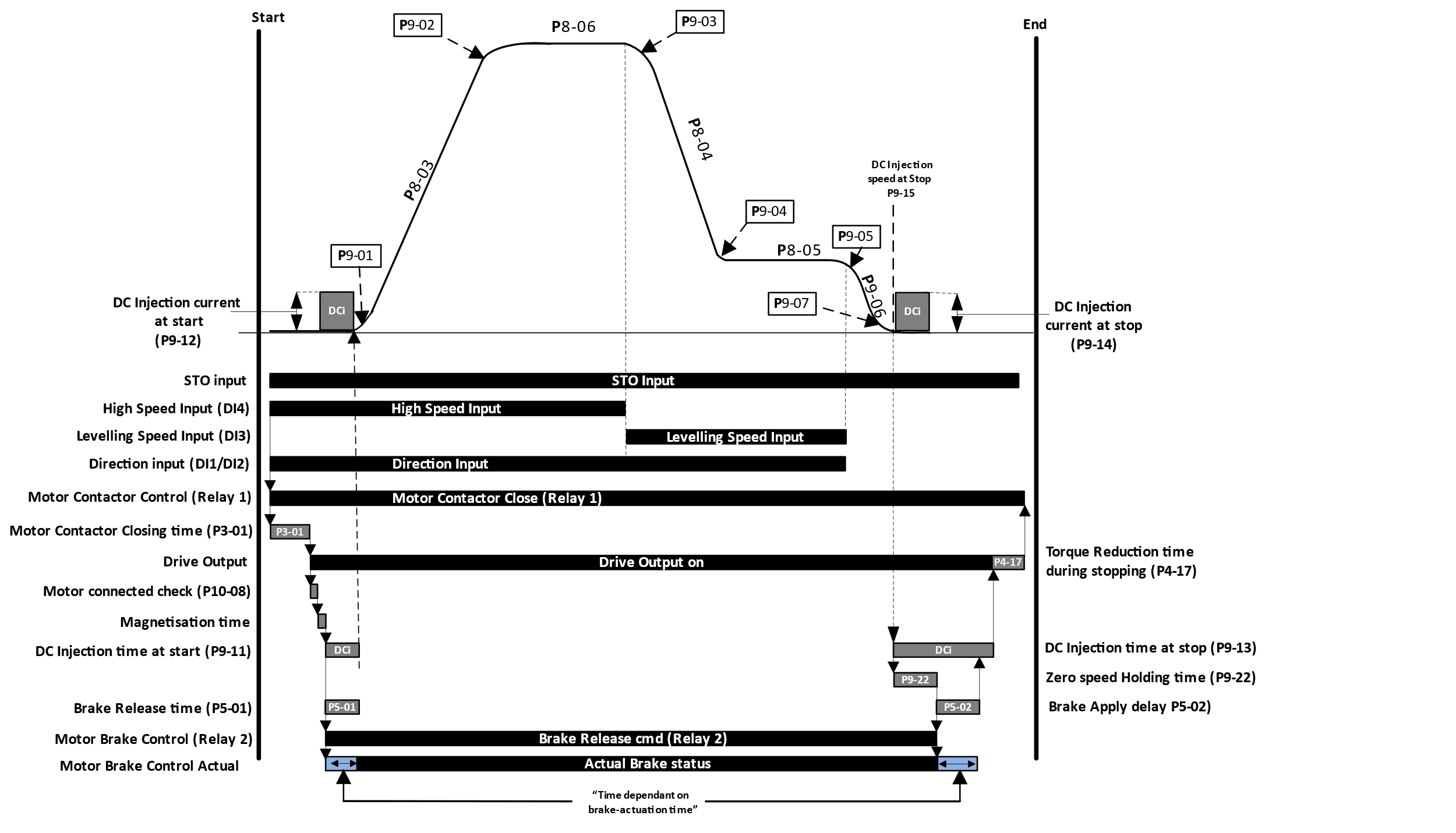
Travel Curve sequence for Geared (Induction) Motors without an Encoder using DC injection for stopping.

Note
Default configuration shown for P1-02 (Digital Input Function Select).
If Macro 9 in P1-02 is chosen, then motor contactor Opens/closes based on the status of terminal DI8 only.
STO Input (STO1 & STO2) Closed by External control system.
Step | Action |
|---|---|
1 | STO Input (STO1 & STO2) Closed by External control system. |
2 | Direction (DI1 or DI2) and Speed reference Inputs (DI4 for high speed as default) given by External Control System. |
3 | Relay 1 closes and thus closes motor contactor (if motor contactor controlled by Drive). |
4 | If not using Motor contactor feedback signal then drive waits for Motor Contactor Closing time (P3-01). |
4 | If Motor contactor feedback signal is being used (see section 15.7.2) then drive waits until this has been received, (if not received within the period of Output Contactor Closing time P3-01 or if feedback signal is received before Step 3 then drive will trip on motor contactor error (CF-Err) |
5 | Drive Output Stage turns-on |
6 | Drive performs motor connected check (P10-08) |
7 | Magnetisation time starts and gives current to the motor |
8 | DC injection current at start (P9-12) and motor bake release time (P5-01) starts And Drive releases brake via relay 2 |
9 | DC injection continues for time set in DC injection time at start (P9-11) |
10 | When DC injection time at start has ended or Brake release time has ended (whichever is the longest) Drive accelerates up to commanded speed reference. |
11 | When High speed input (default DI4) is removed, and levelling speed input is given (default is DI3) the drive decelerates down to levelling speed (P8-05) |
12 | When direction command (DI1/DI2) is removed the drive decelerates down to 0 speed. (P5-03 value ?) |
13 | When the motor reaches zero speed/value set in DC injection speed on stop (P9-15) :
and
|
14 | When Zero speed holding time on disable (P9-22) has ended Relay 2 will open to apply the Electromechanical brake. |
15 | After the time set in brake apply delay (P5-02) or DC Injection time at stop (P9-13) has ended (whichever is the longest) torque drop off will be performed.(P4-17) |
16 | Motor Contactor relay (Relay 1 on the drive as default) will open motor contactor and drive output will turn off. |
The status of the control inputs to/from the drive can be monitored using the following parameters.
P0-01 Display value | 0 | 0 | 0 | 0 | 0 |
|---|---|---|---|---|---|
Function | Digital Input 1 status | Digital Input 2 status | Digital Input 3 status | Digital Input 4 status | Digital Input 5 status |
P0-02 Display value | 0 | 0 | 0 | 0 | 0 |
|---|---|---|---|---|---|
Function | Digital Input 6 status | Digital Input 7 status | Digital Input 8 status | Daux 1 Input Status | Daux 2 Input Status |
P0-03 | STO Input status |
P0-04 | Relay 1 status |
|---|---|
P0-05 | Relay 2 status |
Travel Curve sequence for Geared (Induction) Motors without an Encoder using Brake apply speed for stopping.
Insert new sequencing diagram here.
Note :
Default configuration shown for P1-02 (Digital Input Function Select).
If Macro 9 in P1-02 is chosen, then motor contactor Opens/closes based on the status of terminal DI8 only.
The status of the control inputs to/from the drive can be monitored using the following parameters.
P0-01 Display value | 0 | 0 | 0 | 0 | 0 |
|---|---|---|---|---|---|
Function | Digital Input 1 status | Digital Input 2 status | Digital Input 3 status | Digital Input 4 status | Digital Input 5 status |
P0-02 Display value | 0 | 0 | 0 | 0 | 0 |
|---|---|---|---|---|---|
Function | Digital Input 6 status | Digital Input 7 status | Digital Input 8 status | Daux 1 Input Status | Daux 2 Input Status |
P0-03 | STO Input status |
|---|
P0-04 | Relay 1 status |
|---|---|
P0-05 | Relay 2 status |