Product Familiarisation.
Product Storage
Store the drive in its original box until required. Storage and transportation of the product should be clean and dry and within the temperature range –40°C to +60°C
 Installation following a period of storage
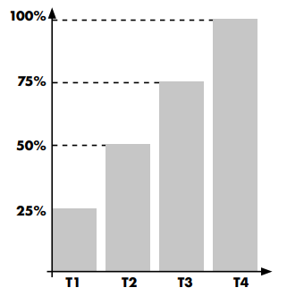
Where the drive has been stored for some time prior to installation or has remained without the main power supply present for an extended period of time, it is necessary to reform the DC capacitors within the drive according to the following table before operation. For drives which have not been connected to the main power supply for a period of more than 2 years, this requires a reduced mains voltage mains voltage to be applied for a time period, and gradually increased prior to operating the drive. The voltage levels relative to the drive rated voltage, and the time periods for which they must be applied are shown in the following table. Following completion of the procedure, the drive may be operated as normal.
 |
Inside the Box
Awaiting box for image here
Show labels
Show User manual
Model Code Key
ODL-3-240095-342SB#
Frame Size
Supply Voltage
2 = 200…240 V AC
4 = 380…480VAC
Output Current Rating
For example, 0095 means 9.5 A.
Number of Input Phases
1 = Single Phase input
3 = 3 Phase input
4 = Internal Brake Transistor
2 = IP20 Enclosure
S = LED Display
Rescue Mode Supply Type
B = UPS or Battery
Encoder Module
E= Encoder Module fitted at manufacturing
0 =Encoder Module not fitted
Product Layout
 |
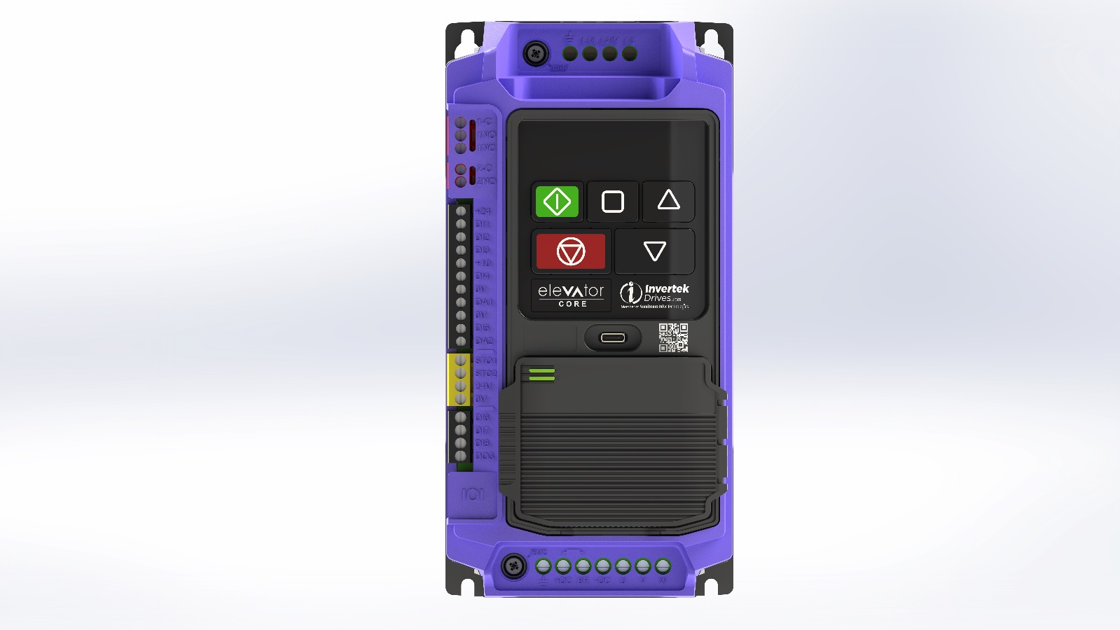
1 | Power Supply Input Terminals |
|---|---|
2 | USB-C Port -Used to light up the drive display and allow drive programming and parameter viewing using a device with USB-C output |
3 | Optional Universal Encoder Module for closed loop operation |
4 | Motor Connection Terminals |
5 | RJ45 Port (NOT FOR ETHERNET!) |
6 | Digital Inputs/Outputs |
7 | Safe Torque-Off Inputs |
8 | Drive Serial Number and Rating |
9 | Digital, Analogue Inputs/Outputs |
10 | Motor Brake Control Output |
11 | Motor Contactor Control Output (Default Function) |
12 | Trip reset Button (In addition to terminal & network reset) |
13 | Input EMC Filter and Varistor Circuit to earth Disconnect |
14 | DC Link EMC Filter Circuit to earth Disconnect |
15 | Brake Resistor Connection Terminals |
16 | Encoder Status LED’s |
17 | QR Code for on-line support documentation |