Parameters and Functions
Parameter Map
There are 12 groups of Parameters within the drive, for ease of parameter navigation the groups are ordered in alignment with the order of work when commissioning a typical system.
When the Elevator drive is reset to factory defaults, or is in its factory supplied state, only Group 1 through to Group 11 Parameters can be accessed, to access parameters in the higher-level groups P11-02 must be set to the same value as P11-04 (Default setting = 101).
Locking Parameters
To Lock parameters set P11-02 to the value in P11-04 (default is 101) then change P11-03 to 1: Locked. Then change P11-02 to 0. Now all parameters except P11-02 and P11-04 are locked and cannot be changed. When a parameter is locked an L will be displayed next to the value when a direction arrow is pressed, and the value cannot be changed.
Unlocking Parameters
To unlock parameters P11-02 must be set to equal the value in P11-04. Once P11-02 is equal to P11-04 then set P11-03 to 0: Unlocked. This unlocks the parameters so they can be changed. If P11-02 does not equal the value in P11-04 thenP11-03 will be unable to be changed and the parameters will remain locked.
Lost Lock code
If you can not remember the code set in P11-04 and P11-03 is set to 1: Locked then the only way to unlock the drive is by factory defaulting the drive. The codes will then return to their default values.
Parameter Group 1 – User I/O, Command Source.
Primary Command Source Selection P1-01
The Setting of Parameters P1-01 defines where the Start, Stop and direction command comes from.
Parameter | Parameter Name | Minimum | Maximum | Default | Units | Visibility Modes | Accessibility | ||||||||||||||||||||||
|---|---|---|---|---|---|---|---|---|---|---|---|---|---|---|---|---|---|---|---|---|---|---|---|---|---|---|---|---|---|
P1-01 | Primary Command Source | 0 | 2 | 0 | - | All | |||||||||||||||||||||||
|
Control Terminal Function Select P1-02
When the Primary Command Source (P1-01) is set to 0 the setting of Parameter P1-02 defines the function of each of the drives control terminals.
Use the Macro table below to select an appropriate value of P1-02 to match the elevator controller output signals.
The status of the control terminals can be monitored using parameter P0-01 and P0-02.
P0-01 Display value | 0 | 0 | 0 | 0 | 0 |
|---|---|---|---|---|---|
Function | Digital Input 1 status | Digital Input 2 status | Digital Input 3 status | Digital Input 4 status | Digital Input 5 status |
P0-02 Display value | 0 | 0 | 0 | 0 | 0 |
|---|---|---|---|---|---|
Function | Digital Input 6 status | Digital Input 7 status | Digital Input 8 status | Daux 1 Input Status | Daux 2 Input Status |
E.g. if P1-02 = 1 then high speed is selected when terminal DI4 is on and P0-01 will show 00010
P1-02 Value ↓ | Drive Control Input Terminals | Speed Source | ||||||||
|---|---|---|---|---|---|---|---|---|---|---|
DI1 | DI2 | DI3 | DI4 | DI5 | DI6 | DI7 | DI8 | |||
0 | User Configurable using group 12. | |||||||||
*1 | *Open Disabled/ Close Forward | *Open Disabled/ Close Reverse | *Open Disabled/ Levelling Speed (P8-05) | *Open Disabled/ High Speed(P8-06) | *Open Disabled/ High Speed 5/Relevelling Speed (P8-12) | *Open Disabled/Inspection Speed (P8-08) | Fault Reset | Rescue Mode Enable | If more than 1 speed selection input is high the highest speed will be used. | |
*2 | *Open Disabled/ Close Forward | *Open Disabled/ Close Reverse | *Open Disabled/ Levelling Speed (P8-05) | *Open Disabled/ High Speed(P8-06) | Ok when closed / E-Trip when open or thermistor trip if thermistor function selected in P1-09 Analog Input 2 (DI5) Format or motor contactor feedback trip if P3-02 is set to 1 (Enabled) Or Brake resistor monitoring trip if P3-06 is set to 1. | *Open Disabled/ Inspection Speed (P8-08) | Fault Reset | Rescue Mode Enable | ||
*For settings 1 and 2 above, the drive will only start if all the below conditions are met:
Note : If more than 1 speed selection input is high the highest speed will be used. | ||||||||||
3 | Open Disabled/ Close Forward | Open Disabled/ Close Reverse | 1 | 0 | 0 | Ok when closed / E-Trip when open or motor contactor feedback trip if P3-02 is set to 1 (Enabled) | Fault Reset | Rescue Mode Enable | P8-06 (High Speed) | |
0 or 1 | 0 | 1 | P8-07 (Intermediate Speed) | |||||||
0 or 1 | 1 | 0 or 1 | P8-08 (Inspection Speed) | |||||||
0 | 0 | 0 | P8-05 (Levelling Speed) | |||||||
4 | Open Disabled/ Close Forward | Open Disabled/ Close Reverse | 1 | 0 | Ok when closed / E-Trip when open or thermistor trip if thermistor function selected in P1-09 Analog Input 2 (DI5) Format or motor contactor feedback trip if P3-02 is set to 1 (Enabled) Or Brake resistor monitoring trip if P3-06 is set to 1. | 0 | Fault Reset | Rescue Mode Enable | P8-06 (High Speed) | |
0 or 1 | 0 | 1 | P8-07 (Intermediate Speed) | |||||||
0 or 1 | 1 | 0 or 1 | P8-08 (Inspection Speed) | |||||||
0 | 0 | 0 | P8-05 (Levelling Speed) |
More Macro settings on next page…
P1-02 Value ↓ | Drive Control Input Terminals | Speed Source | |||||||||||
|---|---|---|---|---|---|---|---|---|---|---|---|---|---|
DI1 | DI2 | DI3 | DI4 | DI5 | DI6 | DI7 | DI8 | ||||||
5 | Open Disabled/ Close Forward | Open Disabled/ Close Reverse | 0 | 0 | 0 | Ok when closed / E-Trip when open or motor contactor feedback trip if P3-02 is set to 1 (Enabled) | Fault Reset | Rescue Mode Enable | P8-05 (Levelling Speed) | ||||
1 | 0 | 0 | P8-06 (High Speed) | ||||||||||
0 | 1 | 0 | P8-07 (Intermediate Speed) | ||||||||||
1 | 1 | 0 | P8-08 (Inspection Speed) | ||||||||||
0 | 0 | 1 | P8-09 (Speed 2) | ||||||||||
1 | 0 | 1 | P8-10 (Speed 3) | ||||||||||
0 | 1 | 1 | P8-11 (Speed 4) | ||||||||||
1 | 1 | 1 | P8-12 (Speed 5) | ||||||||||
6 | Open Disabled/ Close Forward | Open Disabled/ Close Reverse | Off | Speed Reference from Analogue input | Ok when closed / E-Trip when open or thermistor trip if thermistor function selected in P1-09 Analog Input 2 (DI5) Format or motor contactor feedback trip if P3-02 is set to 1 (Enabled) Or Brake resistor monitoring trip if P3-06 is set to 1. | Ok when closed / E-Trip when open or motor contactor feedback trip if P3-02 is set to 1 (Enabled) | Fault Reset | Rescue Mode Enable | Analogue input Ref level | ||||
*7 | *Open Disabled/ Close Forward | *Open Disabled/ Close Reverse | *Open Disabled/ Levelling Speed (P8-05) | Torque Sensor Input | *Open Disabled/ High Speed (P8-06) | *Open Disabled/Inspection Speed (P8-08) | Fault Reset | Rescue Mode Enable | If more than 1 speed selection input is high the highest speed will be used. | ||||
*For setting 7 above, the drive will only start if all the below conditions are met:
Note : If more than 1 speed selection input is high the highest speed will be used. | |||||||||||||
8 | Open Disabled/ Close Forward | Open Disabled/ Close Reverse | 0 | 0 | Brake Release Monitor Input 1 (Only Active if P5-04 Brake Release Monitoring Enable is set to a value of 2) | Brake Release Monitor Input 2 (Only Active if P5-04 Brake Release Monitoring Enable is set to a value of 2) | Fault Reset | Rescue Mode Enable | P8-05 (Levelling Speed) | ||||
1 | 0 | P8-06 (High Speed) | |||||||||||
0 | 1 | P8-07 (Intermediate Speed) | |||||||||||
1 | 1 | P8-08 (Inspection Speed) |
P1-02 Value ↓ | Drive Control Input Terminals | Speed Source | |||||||||||
|---|---|---|---|---|---|---|---|---|---|---|---|---|---|
DI1 | DI2 | DI3 | DI4 | DI5 | DI6 | DI7 | DI8 | ||||||
*9 | Forward Direction Select | Reverse Direction Select | Rescue Mode Enable | 0 | 0 | 0 | Brake Release Monitor Input 1 (Only Active if P5-04 Brake Release Monitoring Enable is set to a value of 2) | Drive Enable | P8-05 (Levelling Speed) | ||||
1 | 0 | 0 | P8-06 (High Speed) | ||||||||||
0 | 1 | 0 | P8-07 (Intermediate Speed) | ||||||||||
1 | 1 | 0 | P8-08 (Inspection Speed) | ||||||||||
0 | 0 | 1 | P8-09 (Speed 2) | ||||||||||
1 | 0 | 1 | P8-10 (Speed 3) | ||||||||||
0 | 1 | 1 | P8-11 (Speed 4) | ||||||||||
1 | 1 | 1 | P8-12 (Speed 5) | ||||||||||
*Setting 9 above has a different operation (in terms of Motor contactor control) to all other operating modes : When a direction cmd is given the motor contactor relay will Close and normal contactor sequence will begin, however the drive will not start until STO inputs are closed and then Digital Input 8 (Drive Enable signal) has been given Also note in this mode the Auto-tune will only begin when a direction signal has been given (Digital Input 1 or Digital Input 2) | |||||||||||||
10 | Open Disabled/ Close Forward | Open Disabled/ Close Reverse | 0 | 0 | Ok when closed / E-Trip when open or thermistor trip if thermistor function selected in P1-09 Analog Input 2 (DI5) Format | Ok when closed / E-Trip when open or motor contactor feedback trip if P3-02 is set to 1 (Enabled) | Ok when closed / E-Trip when open or Brake resistor monitor feedback trip if P3-06 is set to 1 (Enabled) | Rescue Mode Enable | P8-05 (Levelling Speed) | ||||
1 | 0 | P8-06 (High Speed) | |||||||||||
0 | 1 | P8-07 (Intermediate Speed) | |||||||||||
1 | 1 | P8-08 (Inspection Speed) |
Analog Input 1 (DI4) configuration
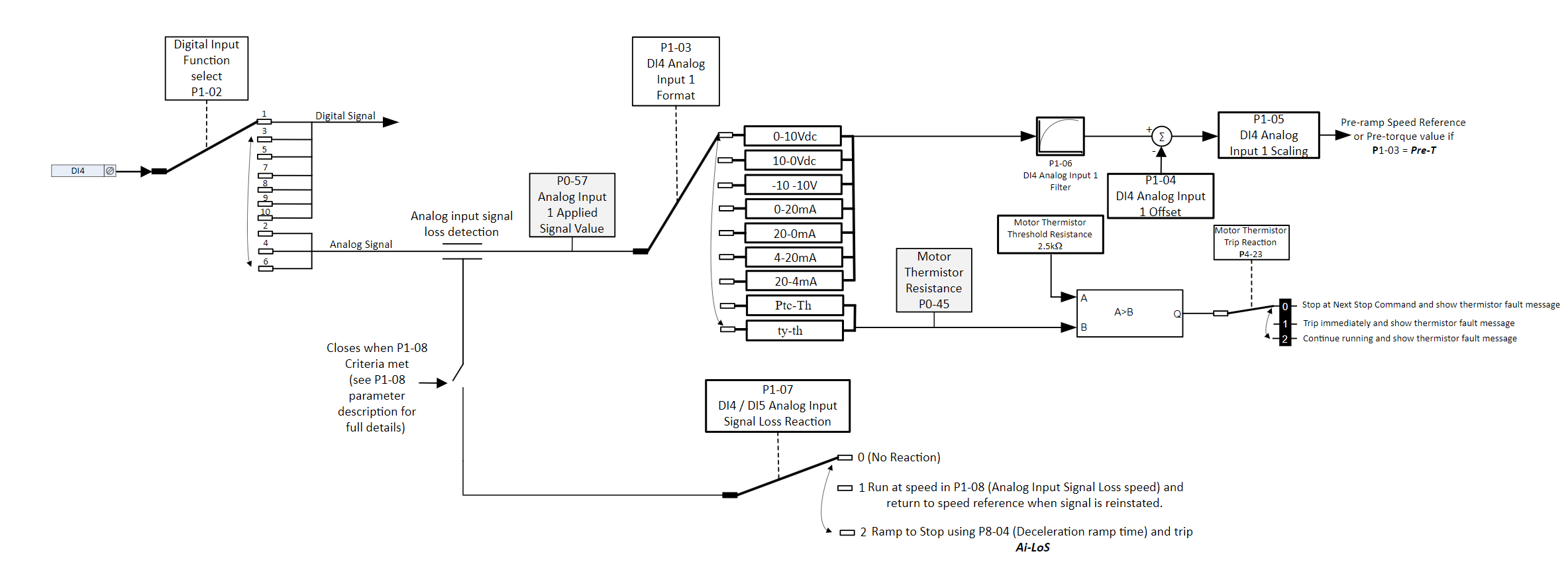
Terminal DI4 can operate from either a Digital Input signal or Analog Input signal, the diagram below illustrates the available settings when operating as an Analog input.
 |
Parameter | Parameter Name | Minimum | Maximum | Default | Units | Visibility Modes | Accessibility | ||||||||||||||||||||||||||||||
|---|---|---|---|---|---|---|---|---|---|---|---|---|---|---|---|---|---|---|---|---|---|---|---|---|---|---|---|---|---|---|---|---|---|---|---|---|---|
P1-03 | DI4 Analog Input 1 Format | - | - | U 0-10 | - | IM PM | RW | ||||||||||||||||||||||||||||||
Note : The input only operates as an Analog input when parameter P1-02 (Digital Input Function Select) is set to 6 or 7.
| |||||||||||||||||||||||||||||||||||||
P1-04 | DI4 Analog Input 1 Offset | -500.0 | 500.0 | 0.0 | % | ||||||||||||||||||||||||||||||||
When Terminal DI4 is operating as an Analog input this parameter allows an offset to be set, the value is set as a percentage of the full-scale range of the input, which is applied to the analog input signal | |||||||||||||||||||||||||||||||||||||
P1-05 | DI4 Analog Input 1 Scaling | 0.0 | 500.0 | 100.0 | % | All | |||||||||||||||||||||||||||||||
When Terminal DI4 is operating as an analogue input Scales the analog input by this factor, e.g. if P1-03 is set for 0 – 10, and the scaling factor is set to 200.0%, a 5 volt input at the control terminal DI4 will result in the drive running at maximum speed (P8-01) The pre and post scaling values can be viewed in parameters P0-87 index 1 and Index 2 | |||||||||||||||||||||||||||||||||||||
P1-06 | DI4 Analog Input 1 Filter | 0.0 | 2.00 | TBC | sec | All | |||||||||||||||||||||||||||||||
This filter helps in situations where the analog input is used for the speed reference or from a Torque sensor and the source signal is noisy which would result in oscillation in speed. The filters primary aim is to make the signal smoother to the internal speed reference but will result in less responsiveness. | |||||||||||||||||||||||||||||||||||||
P1-07 | DI4 Analog Input Signal Loss Reaction | 0 | 2 | 0 | - | All | |||||||||||||||||||||||||||||||
The drive will monitor for speed reference signal loss on the analog input terminals and react according to the setting of P1-07. Speed reference loss is defined as the point when the speed reference falls below a % (as per set in P1-08) of the previous reference for a period of 500ms.
| |||||||||||||||||||||||||||||||||||||
P1-08 | DI4/DI5 Analog Input Signal Loss Speed | 0.0% | 100.00 | 80% | % | All | |||||||||||||||||||||||||||||||
Used in conjunction with P1-07 (DI4/DI5 Analog Input Signal Loss Reaction) and P1-13 (Analog Input 2) Signal Loss Reaction setting 1 and is set as a % of the speed reference prior to the speed reference loss. |
Analog Input 2 (DI5) configuration
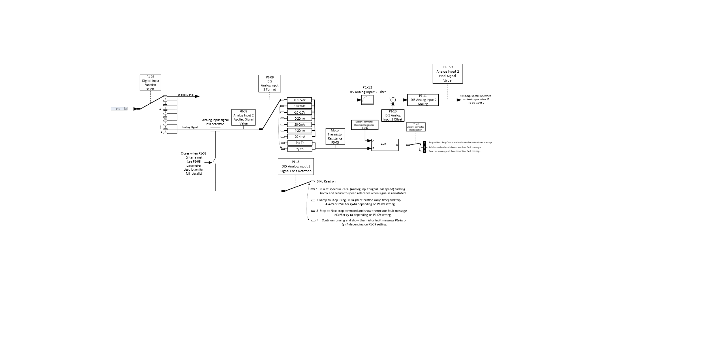
Terminal DI5 can operate from either a Digital input signal or Analog input signal, the diagram below illustrates the available settings when operating as an Analog input.
 |
Parameter Number | Parameter Name | Minimum | Maximum | Default | Units | Visibility Modes | Accessibility | ||||||||||||||||||||||
|---|---|---|---|---|---|---|---|---|---|---|---|---|---|---|---|---|---|---|---|---|---|---|---|---|---|---|---|---|---|
P1-09 | DI5 Analog Input 2 Format | - | - | U 0-10 | - | All | RW | ||||||||||||||||||||||
| |||||||||||||||||||||||||||||
P1-10 | DI5 Analog Input 2 Offset | -500.0 | 500.0 | 0.0 | % | All | RW | ||||||||||||||||||||||
When terminal DI5 is operating as an Analog input this parameter sets an offset, as a percentage of the full-scale range of the input, which is applied to the analog input signal | |||||||||||||||||||||||||||||
P1-11 | DI5 Analog Input 2 Scaling | 0.0 | 500.0 | 100.0 | % | All | |||||||||||||||||||||||
When Terminal DI4 is operating as an analogue input Scales the analog input by this factor, e.g. if P1-03 is set for 0 – 10, and the scaling factor is set to 200.0%, a 5 volt input at the control terminal DI4 will result in the drive running at maximum speed (P8-01) The pre and post scaling values can be viewed in parameters P0-88 index 1 and Index 2 | |||||||||||||||||||||||||||||
P1-12 | DI5 Analog Input 2 Filter | 0.0 | 2.00 | TBC | sec | All | |||||||||||||||||||||||
This filter helps in situations where the analog input is used for the speed reference or from a Torque sensor and the source signal is noisy which would result in oscillation in speed. The filters primary aim is to make the signal smoother to the internal speed reference but will result in less responsiveness. |
Parameter Number | Parameter Name | Minimum | Maximum | Default | Units | Visibility Modes | Accessibility | ||||||||||||
|---|---|---|---|---|---|---|---|---|---|---|---|---|---|---|---|---|---|---|---|
P1-13 | DI5 Analog Input 2 Signal Loss Reaction | 0 | 4 | 0 | - | All | |||||||||||||
Set the reaction method on a signal loss when DI5 is used as analogue input speed reference. Speed reference loss is defined as the point when the speed reference falls below a % (as per set in P1-08) of the previous reference for a period of 500ms.
Conflict with P4-23 ?
|
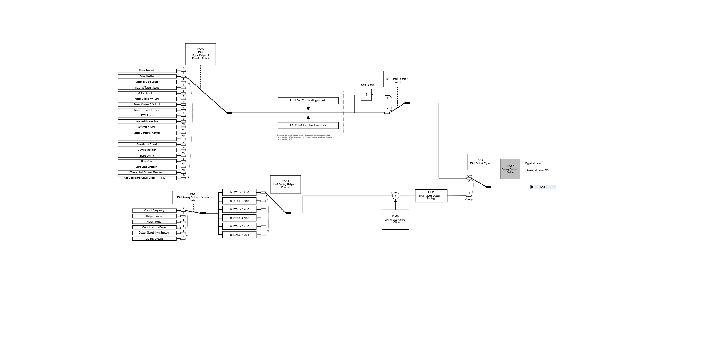
DA1 Output 1 configuration.
DA1 Output 1 is one of two Outputs that can operate as either a Digital Output or an Analog Output as illustrated below.
P1-14 is used to select the Output configuration as either Digital or Analog.
DA1’s function can be selected with P1-15.
 |
Parameter Number | Parameter Name | Minimum | Maximum | Default | Units | Visibility Modes | Accessibility | ||||||||||||||||||||||||||||||||||||||||||||||||||||||||||||||||||||||||||||
|---|---|---|---|---|---|---|---|---|---|---|---|---|---|---|---|---|---|---|---|---|---|---|---|---|---|---|---|---|---|---|---|---|---|---|---|---|---|---|---|---|---|---|---|---|---|---|---|---|---|---|---|---|---|---|---|---|---|---|---|---|---|---|---|---|---|---|---|---|---|---|---|---|---|---|---|---|---|---|---|---|---|---|---|
P1-14 | DA1 Output 1 Type | 0 | 1 | 0 | - | All | |||||||||||||||||||||||||||||||||||||||||||||||||||||||||||||||||||||||||||||
Sets if the output terminal DA1 is to operate as a Digital Output (24Vdc) or as an Analog Output, the Analog type is defined in P1-18 DA1 Analog Output 1 Format.
| |||||||||||||||||||||||||||||||||||||||||||||||||||||||||||||||||||||||||||||||||||
P1-15 | DA1 Digital Output 1 Function Select | 0 | 20 | 1 | - | All | |||||||||||||||||||||||||||||||||||||||||||||||||||||||||||||||||||||||||||||
| |||||||||||||||||||||||||||||||||||||||||||||||||||||||||||||||||||||||||||||||||||
Parameter Number | Parameter Name | Minimum | Maximum | Default | Units | Visibility Modes | Accessibility | ||||||||||||||||||||||||||||||||||||||||||||||||||||||||||||||||||||||||||||
P1-16 | DA1 Digital Output 1 Invert | 0 | 1 | 0 | - | All | |||||||||||||||||||||||||||||||||||||||||||||||||||||||||||||||||||||||||||||
Inverts the logic of DA1 output when operating in digital output mode. | |||||||||||||||||||||||||||||||||||||||||||||||||||||||||||||||||||||||||||||||||||
P1-17 | DA1 Analog Output 1 Source Select | 0 | 5 | 0 | - | All | |||||||||||||||||||||||||||||||||||||||||||||||||||||||||||||||||||||||||||||
| |||||||||||||||||||||||||||||||||||||||||||||||||||||||||||||||||||||||||||||||||||
P1-18 | DA1 Analog Output 1 Source Select | 0 | 5 | 0 | - | All | |||||||||||||||||||||||||||||||||||||||||||||||||||||||||||||||||||||||||||||
| |||||||||||||||||||||||||||||||||||||||||||||||||||||||||||||||||||||||||||||||||||
P1-19 | DA1 Analog Output 1 Scaling | 0 | 500.0 | 100.0 | % | All | |||||||||||||||||||||||||||||||||||||||||||||||||||||||||||||||||||||||||||||
P1-20 | DA1 Analog Output 1 Offset | -500.0 | 500.0 | 0.0 | % | All | |||||||||||||||||||||||||||||||||||||||||||||||||||||||||||||||||||||||||||||
Defines the scaling factor as a %, where output value = (Input value-Offset P1-20) *Scaling factor P1-19 |
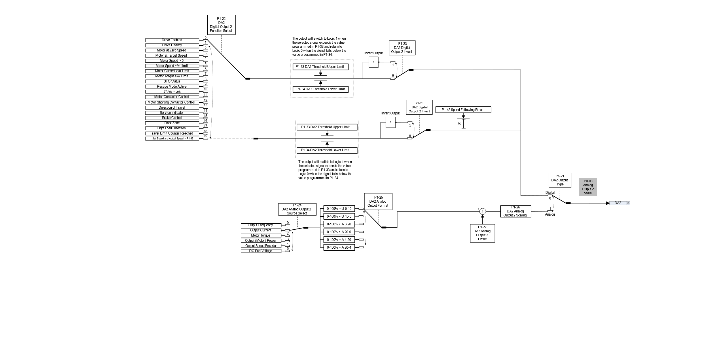
DA2 Output 2 configuration.
DA2 Output 2 is the second of two Outputs that can operate as either a Digital Output or an Analog Output as illustrated below.
P1-21 is used to select the Output configuration as either Digital or Analog.
DA2’s function can be selected with P1-22.
 |
Parameter | Parameter Name | Minimum | Maximum | Default | Units | Visibility Modes | Accessibility | |||||||||||||||||||||||||||||||||||||||||||||||||||||||||||||||||||||
|---|---|---|---|---|---|---|---|---|---|---|---|---|---|---|---|---|---|---|---|---|---|---|---|---|---|---|---|---|---|---|---|---|---|---|---|---|---|---|---|---|---|---|---|---|---|---|---|---|---|---|---|---|---|---|---|---|---|---|---|---|---|---|---|---|---|---|---|---|---|---|---|---|---|---|---|---|
P1-21 | DA2 Output 2 Type | 0 | 1 | 0 | - | All | ||||||||||||||||||||||||||||||||||||||||||||||||||||||||||||||||||||||
Sets if the output from terminal DA2 is to operate as a digital output (24V dc) or as an Analog Output, the Analog type is defined in P1-25 DA2 Analog Output 2 Format.
| ||||||||||||||||||||||||||||||||||||||||||||||||||||||||||||||||||||||||||||
P1-22 | DA2 Digital Output 2 Function Select | 0 | TBC | 0 | - | All | ||||||||||||||||||||||||||||||||||||||||||||||||||||||||||||||||||||||
This defines the output source when DA2 is configured in digital mode.
| ||||||||||||||||||||||||||||||||||||||||||||||||||||||||||||||||||||||||||||
Parameter | Parameter Name | Minimum | Maximum | Default | Units | Visibility Modes | Accessibility | |||||||||||||||||||||||||||||||||||||||||||||||||||||||||||||||||||||
P1-23 | DA2 Digital Output 2 Invert | 0 | 1 | 0 | - | All | R/W | |||||||||||||||||||||||||||||||||||||||||||||||||||||||||||||||||||||
Inverts the logic of DA2 output when operating in digital output mode. | ||||||||||||||||||||||||||||||||||||||||||||||||||||||||||||||||||||||||||||
P1-24 | DA2 Analogue Output 2 Source Select | 0 | 5 | 1 | - | All | R/W | |||||||||||||||||||||||||||||||||||||||||||||||||||||||||||||||||||||
This defines the output source when DA2 is configured in analogue mode.
| ||||||||||||||||||||||||||||||||||||||||||||||||||||||||||||||||||||||||||||
P1-25 | DA2 Analog Output 2 (Terminal 11) Format | 0 | - | U 0-10 | - | All | R/W | |||||||||||||||||||||||||||||||||||||||||||||||||||||||||||||||||||||
| ||||||||||||||||||||||||||||||||||||||||||||||||||||||||||||||||||||||||||||
P1-26 | DA2 Analog Output 2 Scaling | 0 | 500.0 | 100.0 | % | All | R/W | |||||||||||||||||||||||||||||||||||||||||||||||||||||||||||||||||||||
P1-27 | DA2 Analog Output 2 Offset | -500.0 | 500.0 | 0.0 | % | All | R/W | |||||||||||||||||||||||||||||||||||||||||||||||||||||||||||||||||||||
Defines the scaling factor as a %, where output value = (Input value-Offset P1-27)*Scaling factor P1-26 |
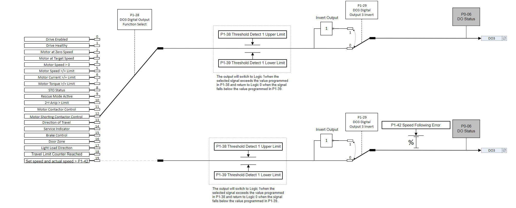
Digital Output 3 Configuration
The drive has one Digital Output that only functions as a Digital Output (DO3) illustrated below.
DO3’s function can be selected from P1-28.
 |
Parameter Number | Parameter Name | Minimum | Maximum | Default | Units | Visibility Modes | Accessibility | ||||||||||||||||||||||||||||||||||||||||||||||||||||||||||||||||||
|---|---|---|---|---|---|---|---|---|---|---|---|---|---|---|---|---|---|---|---|---|---|---|---|---|---|---|---|---|---|---|---|---|---|---|---|---|---|---|---|---|---|---|---|---|---|---|---|---|---|---|---|---|---|---|---|---|---|---|---|---|---|---|---|---|---|---|---|---|---|---|---|---|---|
P1-28 | DO3 Digital Output 3 Function Select | 0 | 19 | 12 | - | All | R/W | ||||||||||||||||||||||||||||||||||||||||||||||||||||||||||||||||||
| |||||||||||||||||||||||||||||||||||||||||||||||||||||||||||||||||||||||||
P1-29 | DO3 Digital Output 3 Invert | 0 | 1 | 0 | - | All | R/W | ||||||||||||||||||||||||||||||||||||||||||||||||||||||||||||||||||
Inverts the logic of DO3 output. |
 User Relays
The drive has 2 relays, they can be used to switch external resistive loads up to :
Relay 1 | 8A/250VAC 10A/30VDC |
|---|---|
Relay 2 | 6A/250VAC 6A/30VDC |
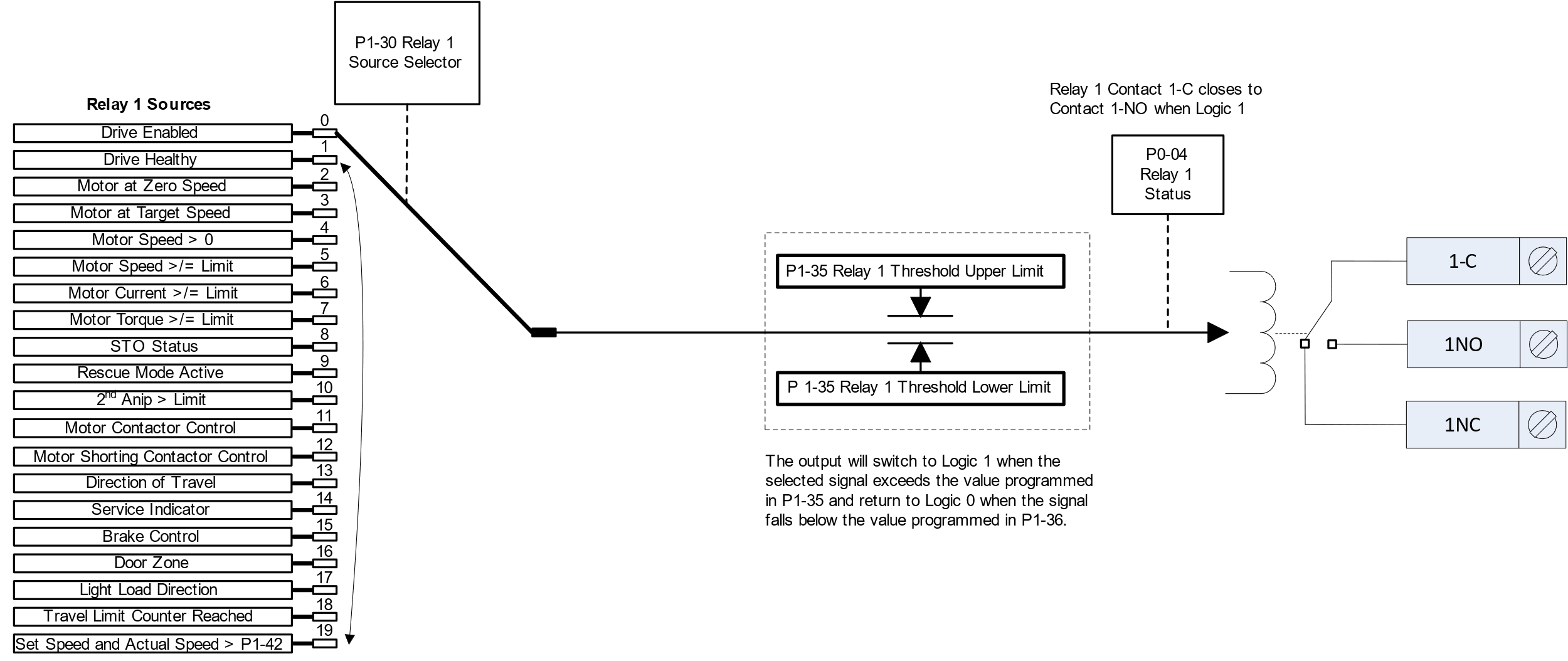
Relay 1 has both normally open and normally closed contacts available; by default, the function of Relay 1
is to control the motor contactors, if an alternative function is required adjust parameter P1-30 (Relay 1 Source Selector).
Relay 2 provides a simple open or closed contact and has a fixed function of motor brake control.
The diagram below illustrates the available settings for Relay 1.
 |
Parameter Number | Parameter Name | Minimum | Maximum | Default | Units | Visibility Modes | Accessibility | ||||||||||||||||||||||||||||||||||||||||||||||||||||||||||||||||||
|---|---|---|---|---|---|---|---|---|---|---|---|---|---|---|---|---|---|---|---|---|---|---|---|---|---|---|---|---|---|---|---|---|---|---|---|---|---|---|---|---|---|---|---|---|---|---|---|---|---|---|---|---|---|---|---|---|---|---|---|---|---|---|---|---|---|---|---|---|---|---|---|---|---|
P1-30 | Relay 1 Source Selector | 0 | 19 | 11 | - | R/W | |||||||||||||||||||||||||||||||||||||||||||||||||||||||||||||||||||
| |||||||||||||||||||||||||||||||||||||||||||||||||||||||||||||||||||||||||
P1-31 | DA1 Threshold Upper Limit | P1-32 | 200.0 | 100.0 | % | All | |||||||||||||||||||||||||||||||||||||||||||||||||||||||||||||||||||
P1-32 | DA1 Threshold Lower Limit | 0.0 | P1-31 | 0.0 | % | All | |||||||||||||||||||||||||||||||||||||||||||||||||||||||||||||||||||
Used in conjunction with settings 5,6,7,10 of Parameter P1-15 DA1 Digital Output 1 Function Select | |||||||||||||||||||||||||||||||||||||||||||||||||||||||||||||||||||||||||
P1-33 | DA2 Threshold Upper Limit | P1-34 | 200.0 | 100.0 | % | All | |||||||||||||||||||||||||||||||||||||||||||||||||||||||||||||||||||
P1-34 | DA2 Threshold Lower Limit | 0.0 | P1-33 | 0.0 | % | All | |||||||||||||||||||||||||||||||||||||||||||||||||||||||||||||||||||
Used in conjunction with settings 5,6,7,10 of Parameter P1-22 DA1 Digital Output 2 Function Select | |||||||||||||||||||||||||||||||||||||||||||||||||||||||||||||||||||||||||
P1-35 | Relay 1 Threshold Upper Limit | P1-36 | 200.0 | 100.0 | % | ||||||||||||||||||||||||||||||||||||||||||||||||||||||||||||||||||||
P1-36 | Relay 1 Threshold Lower Limit | 0.0 | P1-35 | 0.0 | % | ||||||||||||||||||||||||||||||||||||||||||||||||||||||||||||||||||||
Used in conjunction with settings 5,6,7,10 of Parameter P1-30 (Relay 1 Source Selector) Need to define % of what here | |||||||||||||||||||||||||||||||||||||||||||||||||||||||||||||||||||||||||
P1-37 | Digital/Relay Output Hysteresis Band | 0.0 | 25.0 | 0.3 | % | ||||||||||||||||||||||||||||||||||||||||||||||||||||||||||||||||||||
This parameter works in conjunction with P1-15, P1-22, P1-28, P1-30 = 2 or 3 to set a band around the Motor at Target Speed (e.g. P1-15 = 3) or Motor at Zero speed (e.g. P1-15 = 2). When the speed is within this band, the drive is considered to be at Target speed or Zero speed. This function is used to prevent “chatter” on the relay/Digital output if the operating speed coincides with the level at which the digital / relay output changes state. e.g. if P1-30 = 3, P8-01 = 50Hz and P1-36 = 5%, the relay contacts close above 2.5Hz | |||||||||||||||||||||||||||||||||||||||||||||||||||||||||||||||||||||||||
P1-38 | DO3 Threshold Upper Limit | P1-39 | 200.0 | 100.0 | % | All | |||||||||||||||||||||||||||||||||||||||||||||||||||||||||||||||||||
P1-39 | DO3 Threshold Lower Limit | 0.0 | P1-38 | 0.0 | % | All | |||||||||||||||||||||||||||||||||||||||||||||||||||||||||||||||||||
Used in conjunction with settings 5,6,7,10 of Parameter P1-28 DO3 Digital Output 3 Function Select |
Parameter Number | Parameter Name | Minimum | Maximum | Default | Units | Visibility Modes | Accessibility | ||||||
|---|---|---|---|---|---|---|---|---|---|---|---|---|---|
P1-40
| Start Mode Select / Automatic Restart | - | - | Edge-r | - | All | R/W | ||||||
Defines the behaviour of the drive relating to the Direction /Enable digital input and configures the Automatic Restart function.
Edge-r: Following Power on or reset, the drive will not start if a direction input remains closed. The Input must be closed after a power on or reset to start the drive.
Auto-0: Following a Power On or Reset, the drive will automatically start if Direction Input is closed.
Auto-1 to Auto-5: Following a trip, the drive will make up to 5 attempts to restart at 20 second intervals. The drive must be powered down to reset the counter. The number of restart attempts are counted, and if the drive fails to start on the final attempt, the drive will display a fault message (See section 22.1), and will require the user to manually reset the fault. Note: The default reset time is 20 sec’s and can be modified using parameter P1-41 | |||||||||||||
P1-41
| Auto-reset delay time | 1 | 60 | 20 | S | All | R/W | ||||||
Sets the delay time which will elapse between consecutive drive reset attempts when Auto Reset is enabled in P1-40 | |||||||||||||
P1-42
| Speed Following Error | 0.0 | 50.0 | 5.0 | % | All | R/W | ||||||
Used in conjunction with P1-15, P1-22, P1-28 and P1-30 setting 19 as the % error difference between set speed and the actual speed (estimated speed in open loop/encoder speed in closed loop-with encoder) | |||||||||||||
P1-43
| Positive/Negative Logic Select | 0 | 1 | 0 | - | All | R/W | ||||||
Changes the control logic for all digital inputs (including the Universal Encoder module Daux1 and Daux2), | |||||||||||||
Note : STO1 and STO2 Inputs are always positive Logic |
Parameter Group 2 – Communications
Par | Parameter Name | Minimum | Maximum | Default | Units | Visibility Modes | Accessibility | |||||||||||||||
|---|---|---|---|---|---|---|---|---|---|---|---|---|---|---|---|---|---|---|---|---|---|---|
P2-01 | Modbus Slave Address | 0 | 247 | 1 | - | All | R/W | |||||||||||||||
Sets the drive address when communicating over fieldbus to the RJ45 port on the drive. | ||||||||||||||||||||||
P2-02 | Modbus RTU Baud Rate | 9.6 | 115.2 | 115.2 | kbps | All | R/W | |||||||||||||||
Sets the baud rate when Modbus RTU communications is being used. | ||||||||||||||||||||||
P2-03 | Modbus RTU Data Format | 0 | 3 | n-1 | - | All | R/W | |||||||||||||||
| ||||||||||||||||||||||
P2-04 | Communications Loss Timeout | 0.0 | 5.0 | 1.0 | s | All | R/W | |||||||||||||||
Sets the watchdog time period for the communications channel. If a valid telegram is not received by the drive within this time period, the drive will assume a loss of communications has occurred and react as selected below. heartbeat timer | ||||||||||||||||||||||
P2-06 | Modbus RTU Response Delay | 0 | 16 | 0 | char | All | R/W | |||||||||||||||
Allows the user to configure an additional delay between the drive receiving a request via the Modbus RTU interface and transmitting a reply. The value entered represents the delay in addition to the minimum delay permissible according to the Modbus RTU specification, and is expressed as the number of additional characters. | ||||||||||||||||||||||
P2-06 | Communications Loss Action | 0 | 3 | 0 | - | All | R/W | |||||||||||||||
Controls the behaviour of the drive following a loss of communications.
The trip message shown depends on the communications method being used (Sc-FO1-Modbus) or (Sc-FO2-CAN Open) |
P2-13 | USB Port Enable | 0 | 1 | 1 | - | All | R/W |
|---|---|---|---|---|---|---|---|
Determines whether the USB diagnostics comms port is enabled or not. 0 = Disabled 1 = Enabled |
P2-20 | Modbus RTU Messages Per Second | - | - | - | msg/s | All | R/O | |
|---|---|---|---|---|---|---|---|---|
P2-21 | Modbus RTU Messages Processed | - | - | - | - | All | R/O | |
P2-22 | Modbus RTU Errors | - | - | - | - | All | R/O | |
P2-23 | USB-C Messages Processed Per Second | - | - | - | msg/s | All | R/O | |
P2-24 | USB-C Modbus Messages Processed | - | - | - | - | All | R/O | |
P2-25 | USB-C Errors | - | - | - | - | All | R/O | |
Par | Parameter Name | Minimum | Maximum | Default | Units | Visibility Modes | Accessibility | |
P2-50 | Modbus RTU Control Word | - | - | - | - | All | ||
Shows the control word value that has been sent to the drive. More info | ||||||||
P2-51 | Modbus RTU Speed Reference | 0.0 | P8-01 | - | - | All | ||
Shows the speed reference value that has been sent to the drive. More info | ||||||||
P2-52 | Modbus RTU Torque Reference | 0.0 | - | - | - | All | ||
Shows the Torque reference value that has been sent to the drive. More info | ||||||||
P2-53 | Modbus Ramp Rate | 0.0 | - | - | - | All | ||
Shows the Modbus Ramp Rate value that has been sent to the drive. More info | ||||||||
P2-56 | Modbus Status Word | - | - | - | - | All | ||
Shows the Modbus Status word of the drive. More info | ||||||||
P2-57 | Modbus Speed Feedback | - | - | - | - | All | ||
More info | ||||||||
P2-58 | Modbus Motor Current | - | - | - | - | All | ||
More info | ||||||||
P2-59 | Modbus Output Torque | - | - | - | - | All | ||
More info |
Parameter Group 3 – System.
Motor Contactor delay times
Parameter Number | Parameter Name | Minimum | Maximum | Default | Units | Visibility Modes | Accessibility |
|---|---|---|---|---|---|---|---|
P3-01 | Motor Contactor Closing Time/Run Command Delay time | 0 | 5.0 | 0.2 | Sec’s | All | R/W |
Sets a delay time between a Direction signal being applied to the drive and the drive energising the motor, this ensures that the motor contactor has had enough time to change state before current flows from the drive to the motor. Typical values are 0.2 to 0.5 seconds. During the delay time the drive will display “CC” to indicate Contactor Closing time. |
Motor Contactor Monitoring
The drive can monitor the state of the motor contactor by using an auxiliary contact connected to one of the drives digital input terminals, this allows early detection of a motor contactor fault.
The diagram below illustrates the motor Contactor Monitoring function.
 |
Parameter Number | Parameter Name | Minimum | Maximum | Default | Units | Visibility Modes | Accessibility | ||||||||
|---|---|---|---|---|---|---|---|---|---|---|---|---|---|---|---|
P3-02 | Motor Contactor-Monitoring Terminal Enable | 0 | 1 | 0 | n/a | All | R/W | ||||||||
| |||||||||||||||
P3-03 | Motor Contactor Monitoring Errors | 0 | 65536 | 0 | n/a | All | R/O | ||||||||
This value increments by 1 each time there is cF-Err error. The value can only be reset by loading factory/user defaults. |
Brake Resistor Protection
The drive has a built-in thermal overload model for brake resistor overload protection where the drive will trip and stop if the resistor is overloaded (Based on the correct values being set in parameters P3-04 and P3-05), additionally a brake resistor thermal switch can also be monitored through one of the drives digital inputs as illustrated below.
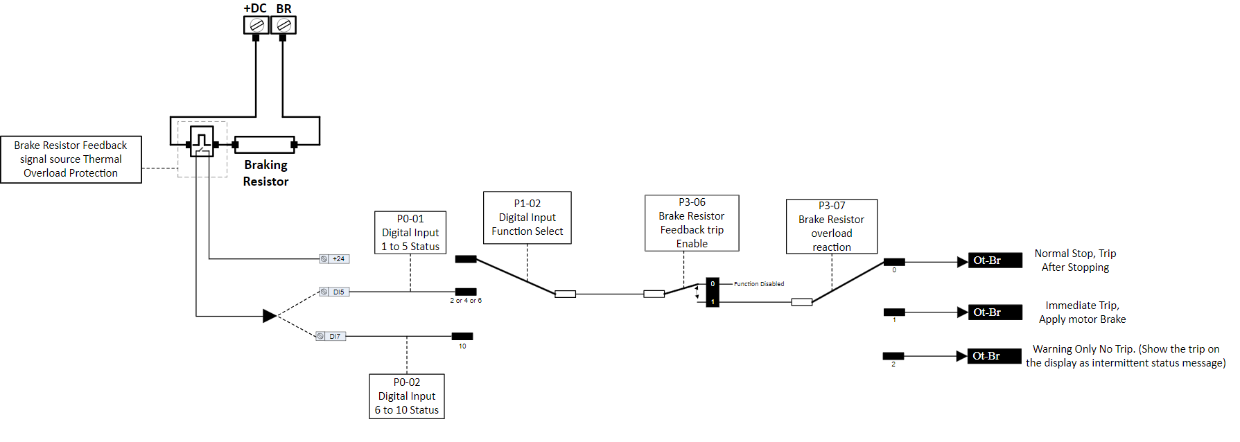 |
Par | Parameter Name | Minimum | Maximum | Default | Units | Visibility Modes | Accessibility | ||||||||
|---|---|---|---|---|---|---|---|---|---|---|---|---|---|---|---|
P3-04 | Brake Resistor Resistance | 0 | 65535 | Drive Rating dependant | Ohms | All | R/W | ||||||||
P3-05 | Brake Resistor Power | 0.0 | 200.0 | 0.0 | kW | All | R/W | ||||||||
For software protection of the connected brake resistor, enter the rated power and resistance of the resistor into the relevant parameters. The drive will then monitor the brake resistor to ensure that it does not operate outside of its designed limits. Where an external thermal protection device is fitted, and software protection is not required. Setting parameter P3-05 to zero will disable the software protection feature. | |||||||||||||||
P3-06 | Brake Resistor Temperature Monitoring Enable | 0 | 1 | 0 | - | All | R/W | ||||||||
This parameter is used when a brake resistor thermal switch is wired back to a digital input set for External trip and tells the drive that the drive should trip on a brake resistor feedback fault (Ot-Br) rather than an external trip. | |||||||||||||||
P3-07 | Brake Resistor Temperature Monitoring trip reaction | 0 | 2 | 0 | - | All | R/W | ||||||||
This parameter defines the drive’s reaction when the Brake resistor overload function has been triggered (Ot-Br)
|
System Mechanical Data/Linear Units operation
The drive will allow the option to program the drive and view the elevator speed in Linear Elevator units e.g., m/s.
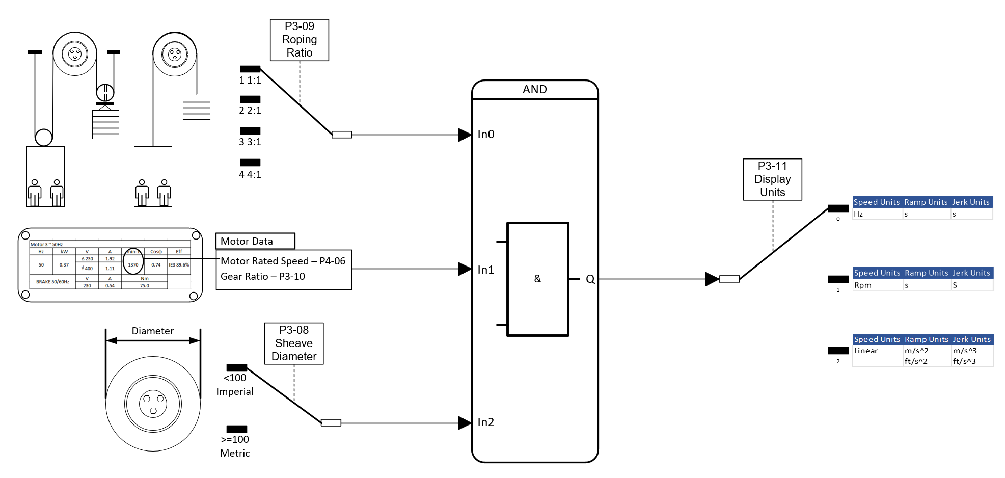 |
To enable this feature the user must program the following parameters:
Motor Rated Speed (P4-06)
Sheave Diameter (P3-08) (<100 drive assumes inches)/(>=100 drive assumes mm)
Roping Ratio (P3-09)
Gear Ratio (P3-10)
For speed feedback information the user can view the real time travel speed by pressing the button until Linear units is shown, and indicated by "L" on the left of the display.
For programming the user can enter the travel speeds (m/s or ft/min), Accel/decel (m/s2 or ft/s2), and Jerk values (m/s3 or ft/s3) in linear units, the units are selected in parameter P3-11
Par | Parameter Name | Minimum | Maximum | Default | Units | Visibility Modes | Accessibility |
|---|---|---|---|---|---|---|---|
P3-08 | Sheave Diameter | 0.0 | 2000.0 | 0.0 | - | All | |
This defines the traction sheave diameter (<100 drive assumes inches)/(>=100 drive assumes mm) | |||||||
P3-09 | Roping Ratio | 1 | 4 | 1 | - | All | |
1 = 1: 1 2 = 2:1 3 = 3:1 4 = 4:1 | |||||||
P3-10 | Gear Ratio | 1.0 | 100.0 | 1.0 | - | All | |
This defines the Gear Ratio of the mechanical Gear. | |||||||
P3-11 | Display Units | 0 | - | All | |||
P3-12 | System Inertia constant | 0 | 600 | 10 | H | All | |
System Load Inertia to Motor Inertia Ratio entered as H= (JTot/JMot) this value can normally be left at the default value (10). |
Direct to Floor Operation
Direct to floor operation automatically calculates the speed profile from the point of when deceleration begins and brings the elevator car directly to the floor, this function is instead of creep to floor operation.
Direct to floor operation is only supported when the drive is used with an Encoder.
Par | Parameter Name | Minimum | Maximum | Default | Units | Visibility Modes | Accessibility | ||||||
|---|---|---|---|---|---|---|---|---|---|---|---|---|---|
P3-13 | Direct to Floor Enable | 0 | 1 | 0 | - | Not V/F | |||||||
| |||||||||||||
P3-14 | Direct to Floor Distance | 0 | tbc | 0 | mm | Not V/F | |||||||
TBD | |||||||||||||
P3-15 | Levelling Distance | 0 | tbc | 0 | mm | Not V/F | |||||||
TBD | |||||||||||||
P3-16 | Measured Floor Distance | 0 | tbc | 0 | mm | Not V/F | |||||||
TBD |
Parameter Group 4 –Motor Setup
| Incorrect adjustment of parameters in group 4 can cause unexpected behaviour of the motor and any connected machinery. |
|---|
Motor Data
Par | Parameter Name | Minimum | Maximum | Default | Units | Visibility Modes | Accessibility | |||||||||||||||
|---|---|---|---|---|---|---|---|---|---|---|---|---|---|---|---|---|---|---|---|---|---|---|
P4-01 | Motor Control Mode | 0 | 4 | 0 | - | All | R/W | |||||||||||||||
| ||||||||||||||||||||||
P4-02 | Motor Rated Voltage/Back EMF-PM Motors | 0 | 250V (230V Unit) 500V (400V Unit) | 230V (230V unit) 400V (400V unit) | Volts | All | ||||||||||||||||
| ||||||||||||||||||||||
P4-03 | Motor Rated Current | 20% of Drive Rated current | (0.1A) | Drive rated current | Amps | All | ||||||||||||||||
Enter the Rated (nameplate) current of the motor |
Par | Parameter Name | Minimum | Maximum | Default | Units | Visibility Modes | Accessibility | ||||||
|---|---|---|---|---|---|---|---|---|---|---|---|---|---|
P4-04 | Motor Rated Frequency | 5.00 | 500.00 | 50Hz | Hz (0.01Hz) | All | |||||||
Rated (nameplate) Frequency of the motor. | |||||||||||||
P4-05 | Motor Poles | 0 | 120 | 2 | - | All | |||||||
Enter the number of motor poles as shown on the motor nameplate.
| |||||||||||||
P4-06 | Motor Rated Speed | 0 | 15000 | 0 | rpm | All | |||||||
Rated (nameplate) speed of the motor. IM motor: Allows drive calculation of the rated slip of the motor (in V/F Mode only) All motors: Changes all speed related parameter values to rpm vs Hz and also required for operating in Linear units mode and when operating with an Encoder. | |||||||||||||
P4-07 | Motor Power Factor Cos-Phi | 0.00 | 0.99 | Rating Dependant | - | All | |||||||
Rated (nameplate) Cos-Phi of the motor. |
Motor Autotune
Par | Parameter Name | Minimum | Maximum | Default | Units | Visibility Modes | Accessibility | ||||||||||||||||
|---|---|---|---|---|---|---|---|---|---|---|---|---|---|---|---|---|---|---|---|---|---|---|---|
P4-08 | Motor Auto-tune Enable | 0 | 7 | 0 | - | All | R/W | ||||||||||||||||
If an Autotune fails, the drive will trip and indicate an Autotune failed code, see section 22.1 for troubleshooting.
In addition to the above "AtF-xx" will indicate if the autotune 4 was unable to measure the back emf of the motor.
If the drive safe torque off inputs are open when the autotune is activated the drive will trip “Atf-07” | |||||||||||||||||||||||
P4-09 | V/F Mode Voltage Boost | 0.0 | 100.0 | 0 | % (Of Motor rated voltage) | All | R/W | ||||||||||||||||
Voltage boost is used to increase the applied motor voltage at low output frequencies, this can help improve low speed and starting torque. Note : P4-01 is set to 1 or 2 then this parameter should be set to 0. | |||||||||||||||||||||||
P4-10 | V/F Characteristic Adjustment Frequency | 0.0 | 100.0 | 0 | % (Of Motor rated frequency) | All | |||||||||||||||||
When operating in V/F mode (P4-01 = 2), this parameter in conjunction with P4-11 sets a frequency point (as a % of P4-04) at which the voltage set in P4-11 (as a % of P4-02) is applied to the motor. Care must be taken to avoid overheating and damaging the motor when using this feature. | |||||||||||||||||||||||
Par | Parameter Name | Minimum | Maximum | Default | Units | Visibility Modes | Accessibility | ||||||||||||||||
P4-11 | V/F Characteristic Adjustment Voltage | 0.0 | 100.0 | 0 | % (Of Motor rated voltage) | All | |||||||||||||||||
Used in conjunction with P4-10 | |||||||||||||||||||||||
P4-12 | Low frequency torque boost current at start | 0.0 | 200.0 | 0 | % | All | |||||||||||||||||
Only effective when operating without an encoder. Allows a Boost current to be applied at start-up and low frequency (limit defined by P4-13), as a % of the motor rated current (P4-03). Injecting some additional current into the motor at low speed to ensure that rotor alignment is maintained and improving operation during starting and low speed with additional holding torque. | |||||||||||||||||||||||
P4-13 | Low frequency Torque Boost current at start Frequency limit | 0.0 | 100.0 | 0 | % | All | |||||||||||||||||
Frequency range for applied boost current (P4-12) as a % of motor rated frequency (P4-04). This sets the frequency cut-off point above which boost current (P4-120 is no longer applied to the motor. | |||||||||||||||||||||||
P4-14 | Low frequency Torque boost current at stop | 0.0 | 200.0 | 0 | % | All | |||||||||||||||||
Only effective when operating without an encoder. Allows a Boost current to be applied at stop and low frequency (limit defined by P4-15), as a % of the motor rated current (P4-03). Injecting some additional current into the motor at low speed to ensure that rotor alignment is maintained and improving operation during stopping with additional holding torque. | |||||||||||||||||||||||
P4-15 | Torque Boost Frequency limit at stop | 0.0 | 100.0 | 0 | % | All | |||||||||||||||||
Only effective when operating without an encoder. Frequency range for applied boost current (P4-14) as a % of motor rated frequency (P4-04). This sets the frequency cut-off point below which boost current is no longer applied to the motor. | |||||||||||||||||||||||
P4-16 | Flux Braking Current Level | 0.0 | 100.0 | 20.0 | % | All | |||||||||||||||||
Additional flux during braking/regen | |||||||||||||||||||||||
P4-17 | Torque Reduction time during stopping | 0.0 | 10.0 | 0.0 | s | All | R/W | ||||||||||||||||
Setting 0 means function is disabled. This parameter helps in reducing the noise in the lift car when the motor brake is applied due to the immediate removal of current. Increasing this value reduces audible noise, setting too high can result in reduced torque and rollback during stopping. | |||||||||||||||||||||||
P4-18 | Maximum Motoring Torque Limit | 0.0 | 400.0 | 200.00 | % | Not V/F | R/W | ||||||||||||||||
When operating in Vector Speed motor control modes (P4-01 = 0, 1, 3), this parameter defines the maximum torque limit. | |||||||||||||||||||||||
P4-19 | Maximum Regenerating Torque Limit | 0.0 | 400.0 | 150.00 | % | Not V/F | R/W | ||||||||||||||||
Active only in Vector Speed motor control modes. Sets the maximum regenerating torque allowed by the drive. | |||||||||||||||||||||||
P4-20 | Slip Compensation Gain in Motoring mode | 0.0 | 400.0 | 100.00 | % | All | R/W | ||||||||||||||||
P4-21 | Slip Compensation Gain in Regenerating mode | 0.0 | 400.0 | 100.00 | % | All | R/W |
Motor Thermal overload Protection.
Internal Motor Thermal overload protection.
The drive has a software-based motor thermal overload function which estimates the motor temperature based on an internal motor thermal model, for the thermal model to work correctly the motor rated current nameplate value must be set in parameter P4-03.
The drive will trip “” when the thermal overload accumulator (P0-31) reaches 100%.
The longest sustainable overload (without an “” trip) is 150% of motor rated current for a period of 60 seconds.
The drive also has a short term overload capacity of 200% for 4 sec’s.
Using a Motor Thermistor for overload protection.
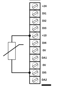
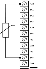
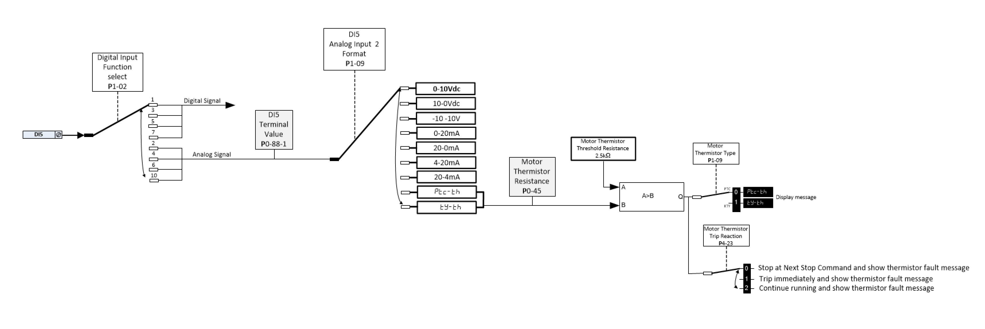
The drive supports PTC and KTY84 type motor thermistors and should be connected to input DI5 as shown below, the input is assigned as thermistor by the setting of parameter P1-02 (Digital Input Function Select) and the type of thermistor is set in parameter P1-09 (DI5 Analog Input 2 Format)
The drive will detect if the motor thermistor becomes short circuit and trip “Sc-th”
| |
The diagram below illustrates the available settings for when a motor thermistor is connected.
 |
Par | Parameter Name | Minimum | Maximum | Default | Units | Visibility Modes | Accessibility | ||||||
|---|---|---|---|---|---|---|---|---|---|---|---|---|---|
P4-22 | Reserved | ||||||||||||
P4-23 | Motor Thermistor Trip Reaction | ||||||||||||
|
Motor Measured Data
These parameters are all read-only and provide the measured values after an auto-tune.
Par | Parameter Name | Minimum | Maximum | Default | Units | Visibility Modes | Accessibility |
|---|---|---|---|---|---|---|---|
P4-24 | Motor Stator Resistance (Rs) | 0.000 | TBC | Rating Dependant | Ohms | All | |
For Geared (Induction) and PM motors: phase to phase stator resistance value in ohms as measured following an Auto-tune. | |||||||
P4-25 | Motor Rotor Resistance (Rr) | 0.000 | TBC | Rating Dependant | Ohms | All | |
For Geared (Induction) motors: phase to phase rotor resistance value in ohms as measured following an Auto-tune. | |||||||
P4-26 | Motor Stator Inductance (Lsd) | 0.1 | TBC | Rating Dependant | mH | All | |
For Geared (Induction) motors: phase stator inductance value. For Gearless (Permanent Magnet) motors: phase d-axis stator inductance in Milli Henry (mH). | |||||||
P4-27 | Motor stator inductance (Lsq) – PM motors only | 0.1 | TBC | Rating Dependant | mH | All | |
P4-28 | Motor Magnetising current (Id rms) | 0.1 | Rating Dependant | Rating Dependant | A | All | |
For Geared (Induction) motors only: magnetizing / no load current, before Auto-tune, | |||||||
P4-29 | Enhanced generator control | 0 | 1 | 0 | - | All | |
0= Disabled 1 = Enabled | |||||||
P4-30 | V/F Mode/PM Magnetising period | - | - | - | - | - | |
Parameter Group 5 – Motor Brake Control and Monitoring
Motor Brake Control
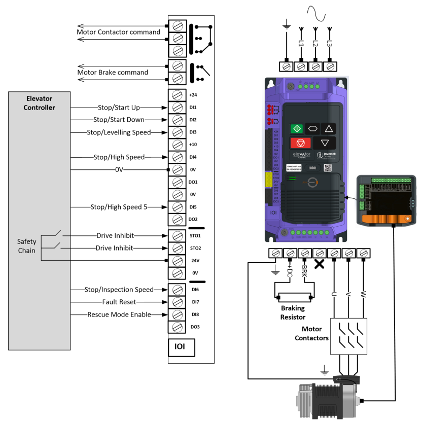 Parameter Group 5 (P5.xx) holds all of the brake control adjustment parameters.
As default Relay 2 is used to control the motors electromechanical brake, the Relay is rated for 250VAC, 30VDC, 5A.
The drive has 2 methods of motor brake control:
When Brake Apply Speed (P5-03) = 0 drive will go through Zero Speed Hold (P9-22) before applying the brake.
When Brake Apply Speed (P5-03) > 0 drive will apply brake as soon as SPEED <= BRAKE APPLY SPEED (P5-03) and will skip Zero Speed Holding time.
Parameter Number | Parameter Name | Minimum | Maximum | Default | Units | Visibility Modes | Accessibility |
|---|---|---|---|---|---|---|---|
P5-01 | Brake Release Time | 0.0 | 5.0 | 0.20 | s | All | |
Sets the delay time, following the contactor Delay time (P3-01) in which it takes for the motor brake to be released (Relay 2) and then drive output frequency ramps up. | |||||||
P5-02 | Brake Apply Delay | 0.0 | 5.0 | 0.20 | s | All | |
P5-03 | Brake Apply Speed | 0.00 | TBC | 0.00 | Hz/rpm/Linear | All | |
Sets the speed at which the drive will signal the motor brake to apply. |
Motor Brake Monitoring
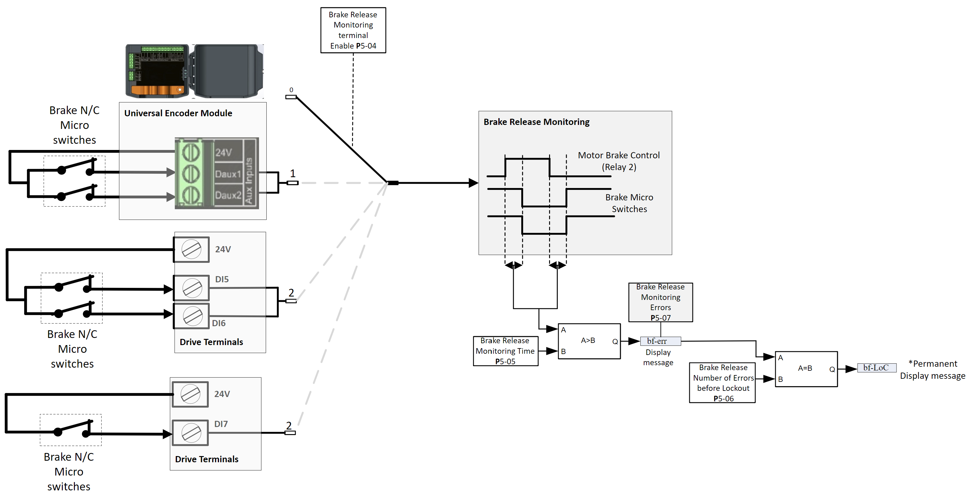
The drive can be used to monitor and verify (using Brake micro switches) the mechanical brake dropping mechanism after each brake release/Apply (Relay 2 of the drive as default), and if verification fails then the drive will trip and prevent the drive reacting to any further run commands, once the trip occurs then it can only be reset by a “competent person“ and not by a normal trip reset or power cycle.
The brake micro switches can be connected to either the Universal Encoder Module or directly to the drive terminals as illustrated below:
The function is enabled using parameter P5-04, when using the drive terminals then a suitable macro also has to be chosen :
P1-02 = 8 (Brake Micro switches connected to DI5 and DI6)
P1-02 = 9 (Brake Micro switches connected to DI7)
 |
Par | Parameter Name | Minimum | Maximum | Default | Units | Visibility Modes | Accessibility |
|---|---|---|---|---|---|---|---|
P5-04 | Brake Release Monitoring Enable | 0 | 2 | 0 | n/a | All | |
0 (Function Off) : Motor Brake Release Monitoring Disabled 1 (Function Enabled) : Motor Brake Release Monitoring Enabled and monitored via Daux 1 Input and Daux 2 Input on the Universal Encoder Module with 2 N/C contacts. 2 (Function Enabled) : Motor Brake Release Monitoring Enabled and monitored via Digital Inputs DI5 and DI6 providing that P1-02 is set to Macro 8 and Digital input DI7 if P1-02 is set to 9. | |||||||
P5-05 | Brake Release Monitoring Time | 0.1 | 5.0 | 0.5 | sec's | All | |
If the monitoring terminal has not changed state in this time (since the brake has been released by relay 2 of the drive) then the drive will trip “bf-Err" or “bf-LoC" (if number of attempts as set in P5-06 has been met) | |||||||
P5-06 | Brake Release Number of Errors Before Lockout | 0 | 5 | 0 | - | All | |
The drive will automatically try to clear the “bf-Err” at 1.5 second intervals for the number of times set, after each attempt the travel sequence will restart, once the number of brake release monitoring errors has reached the number set in this parameter a permanent trip "bF-LoC" will be displayed. | |||||||
P5-07 | Brake Release Monitoring Errors | 0 | 65535 | 0 | - | All | |
Total number of “bf-Err" trips since the drive was installed. |
Note : | bf-Err trip will automatically reset itself after 1.5 second or can be reset manually e.g. direction input/reset input toggled. |
|---|
Method of Operation
When the function (Motor brake monitoring) is enabled, the drive will monitor the chosen terminals as per set in P5-04 and check that each time the brake is commanded to open/close the micro-switches change to the correct state within a set time (P5-05), if the state is incorrect then the drive will display the warning message “Bf-Err" , reset and have another attempt, if after the number of attempts (as set in P5-06) the brake micro switches are indicating the incorrect state then the drive will permanently show the error message “BF-Loc”. Before the lift is put into service, test runs should be performed to ensure that the function works as expected.
In the instance of the permanent error message “BF-Loc” being shown, then it can be cleared as follows:
1. Disable drive.
2. Set P5-04 to Off.
3. Press Mode button.
4. Set P5-04 back to the required monitoring terminal as per set in (P5-04).
Checking for correct Operation
Once the relevant parameters have been programmed (as detailed above) then the “Brake release monitoring” function should be verified for correct operation, this can be carried out by exercising the micro switches/monitoring input (during a low speed run) to simulate the brake not releasing/closing and checking that the ““"/“” error message/s is shown.
Parameter Group 6: Encoder
 |
Par | Parameter Name | Minimum | Maximum | Default | Units | Visibility Modes | Accessibility | ||||||
|---|---|---|---|---|---|---|---|---|---|---|---|---|---|
P6-01 | Encoder Feedback Source | 0 | 1 | 0 | - | All | |||||||
0 = Encoder Feedback Module 1 = Control Terminals (Incremental Single ended Encoder A, B signals only) when P1-02 (Control terminal function select) is set to 11 and the encoder is connected to terminals DI6 and DI7. | |||||||||||||
P6-02 | Encoder Feedback Direction | 0 | 1 | 0 | - | All | |||||||
Changes the direction of the incremental signals of the encoder feedback signal. 0 = A leads B when an Up command is given (Clockwise Direction) 1 = B leads A when an Up command is given (Anti-Clockwise Direction) | |||||||||||||
P6-03 | Encoder Pulses Per Revolution | 256 | 65535 | 256 | - | All | |||||||
Sets the number of Pulses Per Revolution for the encoder according the Encoder nameplate/datasheet. This value must be set correctly to guarantee proper operation of the drive when Encoder feedback mode is enabled (P6-05 >0). Typically values for Incremental encoders are 512, 1024, 2048, 4096 Note : With Endat type Encoder the drive reads from the encoder and populates this parameter value automatically. | |||||||||||||
P6-04 | Encoder Type | 0 | 11 | 0 | - | All | |||||||
0 = No encoder type selected 1= Incremental TTL- Differential (A,/A,B,/B) (RS422) 2 = Incremental HTL-Differential (A,/A,B,/B) (24V) 3 = SinCos with C/D lines 4 = Endat with Incremental signals 5 = Incremental TTL- Differential (A,/A,B,/B, Z,/Z) (RS422) 6 = Incremental TTL (A,B) 7 = Incremental TTL (A,B, Z) 8 = Incremental HTL- Differential (A,/A,B,/B, Z/Z) (24V) 9 = Incremental HTL (A,B) (24V) 10 = Incremental HTL (A,B,Z) (24V) 11 = Endat without Incremental signals Note : For settings 6,7,9,10 where a single ended encoder is used (e.g. A and B) the unused channels of the encoder module must be connected to 0V. | |||||||||||||
P6-05 | Encoder Feedback Enable | 0 | 1 | 0 | - | Not Motor Control Mode 2 (P4-01=2) | |||||||
0 = Encoder Feedback Disabled 1 = Encoder Feedback Enabled Note : Even if P6-05 is set to 0 (Encoder Feedback Disabled) encoder feedback can still be monitored (P0-19) providing P6-03 and P6-04 have been set correctly. Encoder feedback Errors are disabled in this mode of operation. | |||||||||||||
P6-06 | Encoder Feedback Filter at Start | 0 | 20 | 4 | ms | All | |||||||
Helps in situations where there is noise on the Incremental encoder cables, and also allows for setting of higher speed loop gains. | |||||||||||||
P6-07 | Encoder Feedback Filter During Running | 0 | 20 | 4 | ms | All | |||||||
Helps in situations where there is noise on the Incremental encoder cables, and also allows for setting of higher speed loop gains. | |||||||||||||
P6-08 | Encoder Feedback Filter at Stop | 0 | 20 | 4 | ms | All | |||||||
Helps in situations where there is noise on the Incremental encoder cables, and also allows for setting of higher speed loop gains. | |||||||||||||
P6-09 | Encoder Offset | 0.0 | 359.9 | 0.0 | ° | All | R/W | ||||||
As measured by the stationary encoder offset measurement Value will be wrong if the motor poles (P4-05) has been set incorrectly or if an Encoder offset measurement has not been performed. | |||||||||||||
P6-10 | Encoder Count/Position | 0.0 | 359.9 | 0.0 | ° | All | |||||||
P6-11 | Speed Error Trip Level | 0.0 | 100.0 | 10.0 | % | All | |||||||
This parameter defines the maximum permissible speed error between the encoder feedback speed value and the estimated rotor speed calculated by the motor control algorithms. If the speed error exceeds this limit (for the time set in Parameter P6-12 Speed Error Trip Detection Time) , the drive will trip Sp_err. When set to zero, this protection is disabled. Active with and without an Encoder (P6-05 = 0 or 1) | |||||||||||||
Par | Parameter Name | Minimum | Maximum | Default | Units | Visibility Modes | Accessibility | ||||||
P6-12 | Speed Error Trip Detection Time | 0.0 | 5.0 | 0.5 | s | All | |||||||
Used in Conjunction with P6-11 (Speed Error Trip Level) | |||||||||||||
P6-13 | Encoder Module Error Code | ||||||||||||
Displays Error for Universal Encoder Module. | |||||||||||||
P6-14 | Encoder Comms signal Quality | 0.00 | 100.00 | % | |||||||||
Displays the quality of the Encoder feedback signal on Digital Encoders |
Parameter Group 8: Travel Curve
Group 8 Holds all of the Travel curve parameters which are related to movement of the lift (speed, acceleration, deceleration).
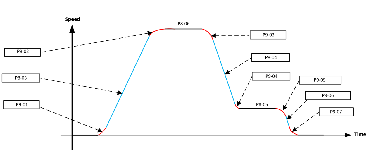 |
Speed Limits
The Values set in all speed, ramp times, jerk times can be set in the user prefered units as per detailed in section 15.7.4
Par | Parameter Name | Minimum | Maximum | Default | Units | Visibility Modes | Accessibility |
|---|---|---|---|---|---|---|---|
P8-01 | Maximum Frequency / Speed Limit | P8-02 | 500.00 | 50.0 (60.0) | Hz/rpm/Linear | All | |
Maximum output motor speed limit. If P4-06 (motor rated speed) >0, the value entered / displayed is in Rpm. If System information has been entered into P3-08 (sheave diameter), P3-09 (roping ratio), P3-10(Gear ratio) then value entered/displayed will be in linear units. This parameter is updated automatically to match the values set in the motor rated frequency (P4-04) and motor rated speed (P4-06), the user can also set the value independently. | |||||||
P8-02 | Minimum Frequency / Speed Limit | 0.00 | P8-01 | 0.00 | Hz/rpm/Linear | All | |
Minimum motor speed limit. |
Acceleration/Deceleration Ramp Times
Par | Parameter Name | Minimum | Maximum | Default | Units | Visibility Modes | Accessibility |
|---|---|---|---|---|---|---|---|
P8-03 | Acceleration Ramp Time | 0.00s | 600s | 2.00s | sec/Linear | All | |
P8-04 | Deceleration Ramp Time | 0.00s | 600s | 2.00s | sec/Linear | All | |
Speed Parameters
The following parameters determine the speed setpoints of the elevator.
Note that when operating in rescue mode the rescue mode speed is set in parameter P7-03.
The required speeds are selected using the drives digital inputs and dependant on the setting of P1-02 (Control Terminal Function select).
Par | Parameter Name | Minimum | Maximum | Default | Units | Visibility Modes | Accessibility |
|---|---|---|---|---|---|---|---|
P8-05 | Levelling Speed | 0.00 | P8-01 | 5.00 | Hz/rpm/Linear | All | |
. | |||||||
P8-06 | High Speed | 0.00 | P8-01 | 50.00 | Hz/rpm/Linear | All | |
P8-07 | Intermediate Speed | 0.00 | P8-01 | 25.00 | Hz/rpm/Linear | All | |
P8-08 | Inspection Speed | 0.00 | P8-01 | 5.00 | Hz/rpm/Linear | All | |
P8-09 | High Speed 2 | 0.00 | P8-01 | 0.00 | Hz/rpm/Linear | All | |
P8-10 | High Speed 3 | 0.00 | P8-01 | 0.00 | Hz/rpm/Linear | All | |
P8-11 | High Speed 4 | 0.00 | P8-01 | 0.00 | Hz/rpm/Linear | All | |
P8-12 | High Speed 5/Relevelling Speed | 0.00 | P8-01 | 0.00 | Hz/rpm/Linear | All | |
Parameter Group 9: Comfort Optimisation
S-ramps/Jerk adjustment
The jerk parameters allow optimisation (smoothing) of the period between speed changes as illustrated in the travel curve below.
 |
Par | Parameter Name | Minimum | Maximum | Default | Units | Visibility Modes | Accessibility |
|---|---|---|---|---|---|---|---|
P9-01 | Acceleration Start Jerk | 0.00s | 5.00s | 1.00s | sec/Linear | ||
P9-02 | Acceleration End Jerk | 0.00s | 5.00s | 1.00s | sec/Linear | ||
P9-03 | Deceleration Start Jerk | 0.00s | 5.00s | 1.00s | sec/Linear | ||
P9-04 | Deceleration End Jerk | 0.00s | 5.00s | 1.00s | sec/Linear | ||
P9-05 | Levelling End Jerk | 0.00s | 5.00s | 1.00s | sec/Linear | ||
P9-06 | Stopping Ramp Time | 0.00s | 600 | 2.00s | sec/Linear | ||
P9-07 | Stopping Jerk | 0.00s | 5.00s | 1.00s | sec/Linear |
Note : The jerk parameters will have an effect on the overall ramp times in the following way :
Total Acceleration Ramp time = P8-03 (Acceleration ramp time) + (P9-01+P9-02 / 2)
Smooth Start Function
The smooth start function allows the starting comfort to be improved in applications with high stiction, in this mode the motor is run at a speed that should be set just above 0 so that it overcomes the stiction before accelerating away towards high speed.
Smooth Start sequence of operation
The smooth start function is activated when a value of >0 is entered into the Smooth start time parameter P9-08 and Smooth Start Speed P9-09.
The smooth start function is only active for the time set in the Smooth start time parameter P9-08.
The smooth start occurs after the brake release and after the brake release delay P5-01.
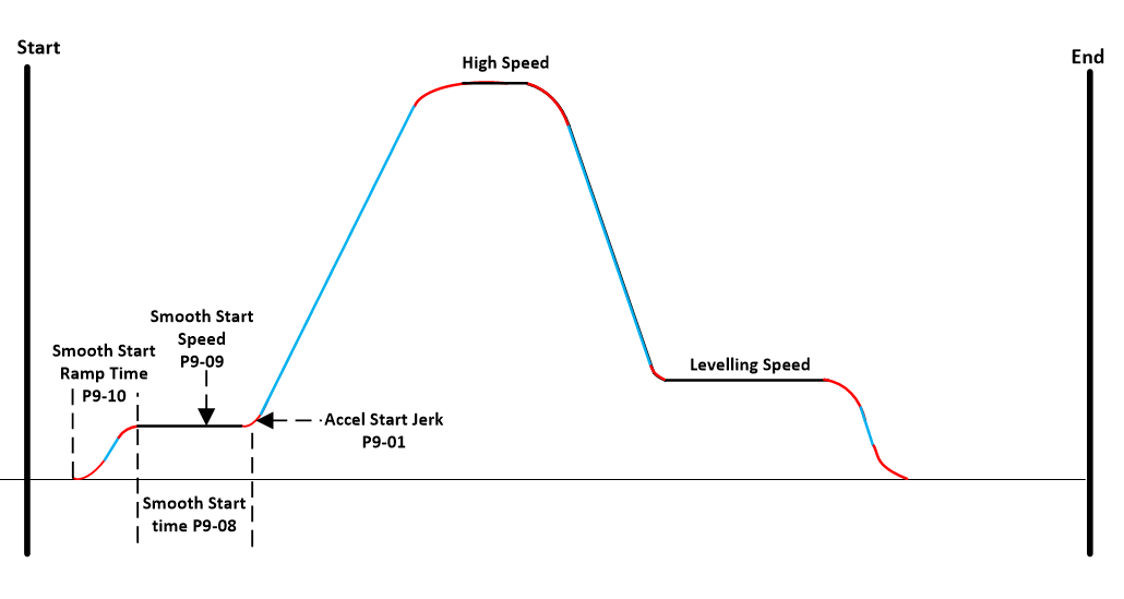 |
Par | Parameter Name | Minimum | Maximum | Default | Units | Motor Modes |
|---|---|---|---|---|---|---|
P9-08 | Smooth Start Time | 0.0 | 5.0 | 0.0 | sec | All |
P9-09 | Smooth Start Speed | 0.00 | P8-01 | 0.00 | Hz/rpm/Linear | All |
P9-10 | Smooth Start Ramp time | 0.00 | 600.00 | 0.50 | sec | All |
Rollback Control
In order to prevent the elevator car from rolling back during start and stopping the drive has a number of features which can be enabled/adjusted.
Parameter P0-17 can be used to monitor the rollback error.
The below table shows which anti-rollback features are available for the various types of systems.
System Type | Motor Control Mode (P4-01) | Encoder Feedback Enabled (P6-05=1) | DC Injection at Start and Stop (P9-11, P9-12, P9-13, P9-14) | Anti-Rollback/Position Lock mode (P9-13, P9-16..P9-21) | Pre-Torque | Torque sensor Input |
|---|---|---|---|---|---|---|
Geared Induction Motor | 0 Advanced Vector IM Speed Control | No | Yes | No | Yes | Yes |
Yes | No | Yes | ||||
1 Simple Vector IM Speed Control | Not Available | Yes | No | Yes | Yes | |
Yes | No | |||||
2 Enhanced V/F IM Speed Control | Not Available | Yes | No | No | No | |
Gearless Permanent Magnet Motor | 3 PM Motor Speed Control | No | No | No | Yes | Yes |
Yes | No | Yes |
Note : DC injection at stop is not active if the brake apply speed (P5-03) has been set to >0.
DC Injection operation to solve rollback
As illustrated in the sequence diagram below DC Injection can be used during starting and stopping to prevent rollback away from the floor and improving floor level accuracy, DC injection applies a DC current to the motor with the goal of creating a braking torque to lock the motor sheave.
DC injection is only suitable for operation with Induction motors operating in open loop (No Encoder).
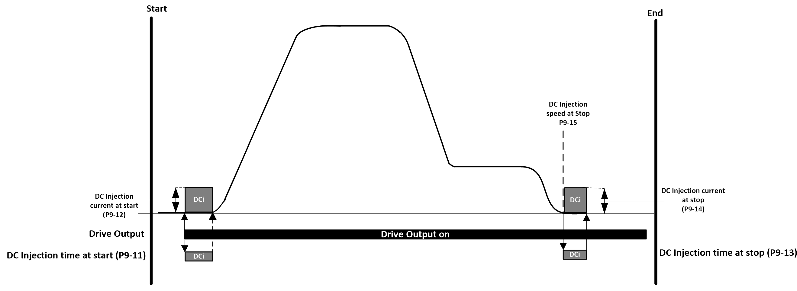 |
DC Injection operation to solve rollback during starting.
Par | Parameter Name | Minimum | Maximum | Default | Units | Visibility Modes | Accessibility |
|---|---|---|---|---|---|---|---|
P9-11 | DC Injection Time at Start | 0.0 | 10.0 | 0.5 | sec's | - | |
Helps eliminate starting rollback in geared open loop applications. Function Disabled if value entered = 0.0 Best value is the shortest time but with the least amount of rollback. | |||||||
P9-12 | DC Injection Current at Start | 0.0 | 200.0 | 50.0 | % of motor rated current | - | |
Helps eliminate starting rollback in geared open loop applications. Function Disabled if value entered = 0.0 Best value is the lowest value but with the least amount of rollback, the higher the value the more heat generated in the motor. |
DC Injection operation to solve rollback during stopping.
Par | Parameter Name | Minimum | Maximum | Default | Units | Visibility Modes | Accessibility |
|---|---|---|---|---|---|---|---|
P9-13 | Position Lock / DC Injection Time at Stop | 0.0 | 10.0 | 0.5 | sec's | - | |
Helps eliminate stopping rollback in geared open loop applications. Function Disabled if value entered = 0.0 Best value is the shortest time but with the least amount of rollback. | |||||||
P9-14 | DC Injection Current at Stop | 0.0 | 200.0 | 50.0 | % of motor rated current | - | |
Helps eliminate stopping rollback in geared open loop applications. Function Disabled if value entered = 0.0 Best value is the lowest value but with the least amount of rollback, the higher the value the more heat generated in the motor and nuisance over current trips. | |||||||
P9-15 | Position Lock / DC Injection Speed at Stop | 0.0 | P8-01 | 0.0 | Hz/RPM | - | |
Helps eliminate stopping rollback in geared open loop applications. DC Injection function is disabled if value entered = 0.0 Best to aim for the lowest suitable value, as too high a value can cause the motor to stop to early resulting in the lift car stopping before reaching the floor. |
Position Lock to solve rollback
For Closed loop Geared and Gearless systems the Position lock function (Rollback Control) can be used during starting and stopping to prevent rollback away from the floor and improving floor level accuracy when stopping.
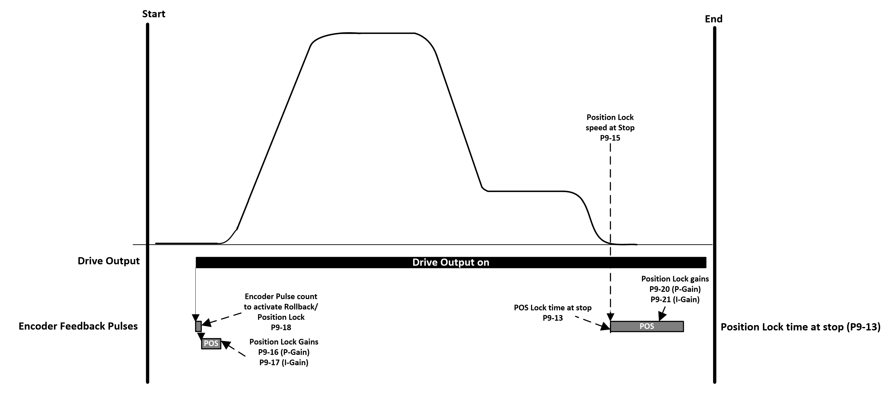 |
Position Lock to solve rollback during starting
Par | Parameter Name | Minimum | Maximum | Default | Units | Visibility Modes | Accessibility | |
|---|---|---|---|---|---|---|---|---|
P9-16 | Rollback Control P-Gain at start | 0.0 | 400.0 | 0.0 | % | All | ||
P9-17 | Rollback Control I-gain at start | 0 | 1000 | 10 | ms | All | ||
P9-18 | Rollback Control activation pulses | 0 | 65535 | 10 | PPR | All | ||
This parameter determines the number of measured encoder feedback pulses before the Rollback Control gain parameters activate. | ||||||||
P9-19 | Rollback Control activation pulses Maximum torque | 0 | 65535 | 128 | % | All | ||
Control the maximum torque during the rollback error period. Rarely needs to be adjusted from default value. | ||||||||
P9-16..P9-18 Helps eliminate starting rollback in geared and gearless closed loop applications. Parameter P0-17 can be used to monitor the rollback error. To reduce rollback, increase P9-16 in steps of 20, if there is no noticeable difference then also increase brake release time P5-01, further improvement can be made by reducing P9-18 (Rollback Control activation pulses) Tip : Incorrect settings will identify as audible noise, vibration, start jerk. |
Position Lock to solve rollback during stopping
Par | Parameter Name | Minimum | Maximum | Default | Units | Visibility Modes | Accessibility |
|---|---|---|---|---|---|---|---|
P9-20 | Rollback Control P-Gain at stop | 0.0 | 400.0 | 0.0 | % | All | |
P9-21 | Rollback Control I-Gain at stop | 0 | 1000 | 10 | ms | All | |
P9-20 and P9-21 Helps eliminate stopping rollback in geared and gearless closed loop applications. Parameter P0-17 can be used to monitor the rollback error. To reduce rollback increase P9-20 and reduce P9-21 until the point where rollback has been eliminated, incorrect settings will identify as audible noise, vibration, start jerk. |
P9-22 | Zero Speed Holding Time on disable | 0.0 | 100.0 | 0.2 | s | All | |
|---|---|---|---|---|---|---|---|
Sets the zero speed holding time, between reaching the DC Injection speed at Stop P9-15 and the brake command being given to engage the brake |
Speed Loop Gains
The setting of the speed loop gains defines how closely the actual motor speed follows the given speed reference, in the case of an Elevator the correct setting of the speed loop gains is critical in order to provide optimum comfort levels.
The speed loop gains are available in all motor operating modes except “Enhanced V/F IM Speed Control mode” (P4-01=2).
In general the default speed loop gains should provide a good starting point.
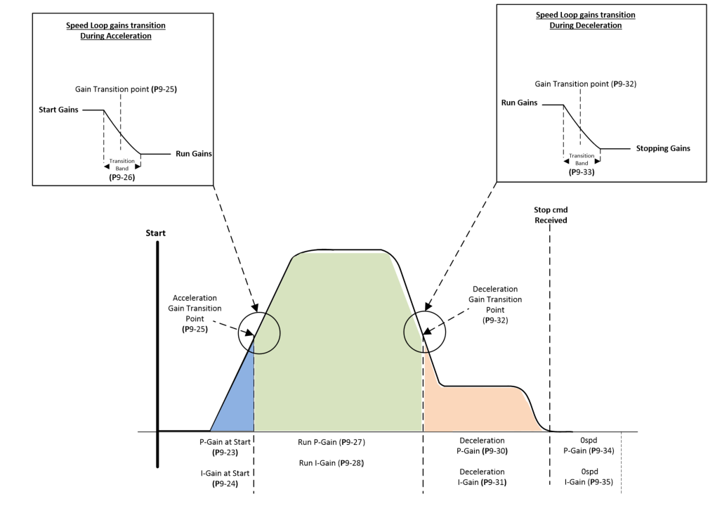 |
Par | Parameter Name | Minimum | Maximum | Default | Units | Visibility Modes | Accessibility |
|---|---|---|---|---|---|---|---|
P9-23 | Speed Loop Proportional Gain at start | 0.00 | 400.00 | 50.0 | % | All | |
P9-24 | Speed Loop Integral Gain at start | 0 | 1000 | 50 | ms | All | |
P9-25 | Speed Loop Gain Transition Speed during acceleration | 0.00 | P8-01 | 0.00 | Hz/RPM/Linear | All | |
P9-26 | Speed Loop Gain Transition Bandwidth during acceleration | 0.00 | P8-01 | 0.00 | Hz/RPM | All | |
P9-27 | Speed Loop Proportional Gain during Run | 0.00 | 400.0 | 50.0 | % | All | |
P9-28 | Speed Loop Integral Gain during Run | 0.00 | 1000 | 50 | ms | All | |
P9-29 | Speed Loop Differential Gain during Run | 0.00 | 400.0 | 0.00 | % | All | |
Generally this parameter does not need to be adjusted. | |||||||
P9-30 | Speed Loop Proportional Gain During Deceleration Below Transition Point | 0.00 | 400.0 | 50.0 | % | All | |
P9-31 | Speed Loop Integral Gain During Deceleration Below Transition Point | 0.00 | 1000 | 20 | ms | All | |
P9-32 | Speed Loop Gain Transition Speed During Deceleration | 0.00 | P8-01 | 0.00 | Hz/RPM/Linear | All | |
P9-33 | Speed Loop Gain Transition Bandwidth During Deceleration | 0.00 | P8-01 | 0.00 | Hz/RPM | All | |
P9-34 | Speed Loop Proportional Gain at Zero Speed | 0.00 | 400.0 | 50.0 | % | All | |
P9-35 | Speed Loop Integral Gain at Zero Speed | 0.00 | 1000 | 50 | ms | All |
Speed Loop Gains adjustment
Tuning of the Speed Loop Gains should be performed with varying load conditions (i.e. No load & Full load).
Parameter P0-16 shows the speed error to help identify how closely the motor speed is following the speed reference, this can aid tuning of the speed loop throughout the travel curve.
In general the speed loop gains at each segment of the travel curve should be adjusted so that optimum travel comfort is achieved.
Increase the Proportional Gains to achieve the required travel comfort (e.g. No speed overshoot when reaching high speed), the upper limitation of the setting will normally show as vibration/Speed Oscillations/Motor noise.
Decrease the Integral Gains) to achieve the required travel comfort, the lower limitation will normally show as speed instability/vibration.
The diagram below shows a typical scenario showing how speed overshoot at the end of the acceleration ramp and speed oscillation during floor approach was solved:
Motor Pre-Torque
Par | Parameter Name | Minimum | Maximum | Default | Units | Visibility Modes | Accessibility |
|---|---|---|---|---|---|---|---|
P9-36 | Motor Pre-Torque in Clockwise Direction | -100.00 | 100.00 | 0.0 | % | All | |
% of motor rated current | |||||||
P9-37 | Motor Pre-Torque in Counter-Clockwise Direction | -100.00 | 100.00 | 0.0 | % | All | |
% of motor rated current | |||||||
P9-38 | Speed Error Deadband | 0.0 | 100.0 | 2.0 | % | All | |
Load-Cell Input
Parameter Group 10: Extended Functions
Par | Parameter Name | Minimum | Maximum | Default | Units | Visibility Modes | Accessibility |
|---|---|---|---|---|---|---|---|
P10-01 | Short Floor Operation | 0 | 1 | 0 | - | - | |
0 = Function Disabled 1 = Function Enabled |
Short Floor Operation
In a normal elevator travel profile, the drive will be travelling at the Run Speed when the levelling input is received (essentially, the Run Speed input is removed). If the levelling input (run speed input removed) is received prior to the drive having reached the Run Speed (e.g., whilst still accelerating) the short floor operation will work to reduce the Elevator travel time by automatically adjusting the speed to reach the floor in a shorter time.
Normal Elevator travel profile
 |
If the Output Frequency is > 40% of Run Speed when levelling Input received
In this case, the drive will hold the present output frequency for the time period calculated (Line A) based on the travel distance from Run Speed to the present output frequency, before decelerating to the levelling speed.
 |
If the Output Frequency Output Frequency is < 40% of Run Speed when levelling Input received
In this case, the drive will accelerate to 40% of the Run Speed and maintain this frequency for a time period calculated (Line A) based on the travel distance from Run Speed to the present output frequency, before decelerating to the levelling speed.
 |
Early Door Opening
The Early Door opening function is used to provide the elevator controller with a signal (From a digital output) at a set speed to open the elevator doors prior to reaching the exact floor level (saving time at stop to open the doors).
Example below showing DO3 setup for Early door opening.
 |
Par | Parameter Name | Minimum | Maximum | Default | Units | Visibility Modes | Accessibility |
|---|---|---|---|---|---|---|---|
P10-02 | Door Zone | 0.0 | 100.0 | 0.0 | (% of motor rated speed) | All | |
Any of the drives digital outputs or relays can be set to give an output when the door zone speed condition has been met (setting 16), example of using Digital output 3 shown above. The output will only come on during deceleration approaching the floor. |
Rope Wear Counter
The rope wear counter counts the number of direction changes to monitor and indicate rope lifetime and when maintenance/replacement of ropes is required.
Example below showing DO3 setup for Indicating Rope Wear Counter limit (P10-05) has been reached.
 |
Par | Parameter Name | Minimum | Maximum | Default | Units | Visibility Modes | Accessibility |
|---|---|---|---|---|---|---|---|
P10-03 | Travel Direction Change Counter (Non-Resettable) | 0.00 | 0.00…10.0M | 0.00 | - | - | |
Counts up by 1 every time there is a change in travel direction. | |||||||
P10-04 | Travel Direction Change Counter (Resettable) | 0.00 | 0.00…10.0M | 0.00 | - | - | |
Counts up by 1 every time there is a change in travel direction. | |||||||
P10-05 | Travel Direction Change Counter Limit | 0.00 | 0.00…10.0M | 0.00 | - | - | |
When the value entered in this parameter has been reached a warning message (tr-Lt) is shown on the drive display and a digital output or Relay will come on (If output source is set for 18 - Travel Limit Counter Reached - example of using Digital output 3 shown above). | |||||||
P10-13 | Travel Direction Change Counter Limit Reached | 0 | 1 | 0 | - | - | |
0 = Travel Direction Change Counter Limit Not Reached 1 = Travel Direction Change Counter Limit Reached |
Travel Counter
Par | Parameter Name | Minimum | Maximum | Default | Units | Visibility Modes | Accessibility |
|---|---|---|---|---|---|---|---|
P10-06 | Travel Counter Reset | 0 | 1 | 0 | - | - | |
0 : Keeps the travel counter value. 1 : Resets the Travel counter value (Returns to 0 when completed) | |||||||
P10-07 | Number of Travels | 0 | TBC | - | - | - | |
Counts up by 1 on every drive enable signal given |
Motor Connected Check
Par | Parameter Name | Minimum | Maximum | Default | Units | Visibility Modes | Accessibility |
|---|---|---|---|---|---|---|---|
P10-08 | Motor Connected Check | 0.0 | 100.0 | 5.0 | % | - | |
To ensure that the motor is connected, the drive has a function which checks that at each start command all 3 phases of the motor are connected prior to releasing the electro-mechanical brake. This function checks for breaks in the connection between the drive and the motor, for example a broken cable or a faulty contactor. The drive will trip “OUT-Phx” if the drive detects the motor is not connected, where x is the phase that is missing e.g. "OUT-PhU" Setting 0.0 means function is disabled. | |||||||
Guidance on setting. | |||||||
The default value is in general suitable for most applications, this value can be reduced to reduce the audible noise when the test is performed. The correct value is one in which the audible noise level is acceptable, but the drive still detects a missing motor phase should it not be connected. |
Anti-Stall
The Anti-Stall function prevents overcurrent trips should the acceleration time be too short to accelerate the load.
Par | Parameter Name | Minimum | Maximum | Default | Units | Visibility Modes | Accessibility | ||||
|---|---|---|---|---|---|---|---|---|---|---|---|
P10-09 | Anti-Stall | 0 | 1 | 1 | - | - | |||||
| |||||||||||
P10-10 | Anti-Stall Limit | 100.0 | 250.0 | 100.0 | % | - | |||||
Set as a % of motor rated current | |||||||||||
P10-11 | Anti-Stall Hysteresis | 0 | 50 | 10 | % | - | |||||
Set as a % of motor rated current | |||||||||||
Guidance on setting. | |||||||||||
The value set should be below the value set in the torque limit parameters P4-18 and P4-19 so that the 2 functions don’t conflict with each other. How does the user know the anti-stall condition is active ? |
Motor Overspeed governor Test
Parameter P10-12 can be used for testing of overspeed governors, normally performed during initial installation or scheduled inspections.
Par | Parameter Name | Minimum | Maximum | Default | Units | Visibility Modes | Accessibility |
|---|---|---|---|---|---|---|---|
P10-12 | Overspeed Governor test speed | 0.0 | 125 | 0.0 | % | - | |
Once a value of >0.0 has been entered, the next run command from the controller to the drive will result in the motor running at the value set in terms of a % of the value set in the High-Speed parameter (P8-06), then at the next stop command the value of the parameter will return to 0.0 automatically so that the test is not repeated, and normal operation is resumed. Need safety warning here !!! |
Parameter Group 11: Drive Configuration
On-board Back-up of user parameter settings
The drive can store a backup of the user parameter settings, this is useful in the event of someone inadvertently adjusting the drive operational parameters and allows for the parameter settings to be returned exactly as per the original installation.
Once the drive has been programmed for the application, setting parameter P11-01 to a 1 will save the drive parameters as user default parameters.
Parameter number | Parameter Name | Minimum | Maximum | Default | Units | Visibility Modes | Accessibility | ||||||
|---|---|---|---|---|---|---|---|---|---|---|---|---|---|
P11-01 | Save User Parameters as Defaults | 0 | 2 | 0 | - | - | |||||||
|
Parameter access lock
To prevent un-authorised editing of parameter settings the drive parameters can be made read-only and if required can also locked by an access code.
Parameter number | Parameter Name | Minimum | Maximum | Default | Units | Visibility Modes | Accessibility |
|---|---|---|---|---|---|---|---|
P11-02 | Extended Menu Access Code | 0 | 30000 | 0 | - | - | |
The value entered in parameter P11-02 determines which parameter groups are accessible by the user. By Default if : P11-02 = 0 = Level 1 parameter groups can be accessed. P11-02 = 101 = Level 2 parameter groups can be accessed. Level 1 access includes groups 0 through to group 11. Level 2 access includes groups 0 through to group 12. The code for Level 2 can be changed by the user by setting the desired value into parameter P11-04 | |||||||
P11-03 | Parameter Access Lock | 0 | 1 | 0 | - | - | |
0 = All parameters can be accessed and changed 1 = Parameters are made read only (apart from P11-02 and P11-04) | |||||||
P11-04 | Level 2 Access Code Definition | 0 | 9999 | 0 | - | - | |
Enter your chosen access code here (>0) which once set must be entered in P11-02 to access parameter group 2 Once set this parameter will become hidden until the same value is entered into P11-02 |
NOTE: When the menu access code (P11-04) is changed then it must be retained in a safe location for further reference to allow further configuration or service. Forgotten access codes can be cleared by returning the drive back to default settings. A default is performed by pressing STOP, UP and DOWN buttons simultaneously for more than 2 seconds. This will clear all drive parameters, including the security codes back to default values.
Parameter number | Parameter Name | Minimum | Maximum | Default | Units | Visibility Modes | Accessibility |
|---|---|---|---|---|---|---|---|
P11-05 | Effective Switching Frequency | 2.0 | 10.0 | 10.0 | 0.1kHz | - | R/W |
IGBT Switching Frequency. Higher switching frequencies reduce the audible ‘ringing’ noise from the motor, and improve the output current waveform, at the expense of increased drive losses. | |||||||
P11-06 | Auto Thermal Management | 2.0 | 10.0 | 2.0 | kHz | - | R/W |
This parameter defines the minimum effective switching frequency which the drive will use when the drive auto- switches down the switching frequency (Based on Heatsink Temperature and motor current) in order to reduce the losses and heat from the power stage. | |||||||
P11-07 | Thermal Overload Value Retention | 0 | 1 | 0 | - | - | R/W |
0: Disabled (No retention) 1: Enabled (retention). An internal overload accumulator (P0-31) monitors the motor output current over time, and will trip the drive if the usage exceeds the thermal limit. When P11-07 is 0, removing the power supply from the drive and re-applying will reset the value of the accumulator. When P11-07 is 1, the value is retained during power off. | |||||||
P11-08 | Enable PLC Operation | 0 | 1 | 0 | - | - | R/W |
0 = Disabled 1 = Enabled |
Parameter Number | Parameter Name | Minimum | Maximum | Default | Units | Visibility Modes | Accessibility | ||||||||||||||||||||||
|---|---|---|---|---|---|---|---|---|---|---|---|---|---|---|---|---|---|---|---|---|---|---|---|---|---|---|---|---|---|
P11-09 | Output Phase Sequence | 0 | 1 | 0 | - | - | |||||||||||||||||||||||
0 = U, V, W 1 = U, W, V. Direction of motor rotation when operating in a forward direction will be reversed. | |||||||||||||||||||||||||||||
P11-10 | Modulation Type | 0 | 2 | 0 | - | - | |||||||||||||||||||||||
0 = 3-Phase 1 = 2-Phase 2 = Auto | |||||||||||||||||||||||||||||
P11-11 | Display Scaling Factor | -30.000 | 30.000 | 0.000 | - | - | |||||||||||||||||||||||
P11-11 & P11-12 allow the user to program the drive to display an alternative output unit scaled from an existing parameter, e.g. to display speed in metres per second based on the output frequency. This function is disabled if P11-11 is set to 0. If P11-11 is set >0, the variable selected in P11-12 is multiplied by the factor entered in P11-11, and displayed whilst the drive is running, with a ‘c’ to indicate the customer scaled units. | |||||||||||||||||||||||||||||
P11-12 | Display Scaling Source | 0 | 6 | 2 | - | - | |||||||||||||||||||||||
|
Parameter number | Parameter Name | Minimum | Maximum | Default | Units | Visibility Modes | Accessibility | |||||||||||||||||||
|---|---|---|---|---|---|---|---|---|---|---|---|---|---|---|---|---|---|---|---|---|---|---|---|---|---|---|
P11-13 | Reset cooling fan run-time | 0 | 1 | 0 | - | - | ||||||||||||||||||||
Setting to 1 resets the internal Fan run-time counter to zero (as displayed in P0-65). | ||||||||||||||||||||||||||
P11-14 | Cooling fan control | 0 | 1 | 0 | - | - | ||||||||||||||||||||
| ||||||||||||||||||||||||||
P11-15 | Cooling Fan run time after disable | 0 | 600 | 0 | Sec’s | - | ||||||||||||||||||||
This parameter defines the fan run time after disable regardless of internal temperature. 0 = Disabled | ||||||||||||||||||||||||||
P11-16 | Reset kWh meter | 0 | 1 | 0 | - | - | ||||||||||||||||||||
Setting to 1 resets the internal energy consumption kWh meter to zero (as displayed in P0-58 and P0-59). | ||||||||||||||||||||||||||
P11-17 | Service time interval | 0 | 65535 | 0 | h | - | ||||||||||||||||||||
This defines the total number of run time hours which must elapse before the Service indicator output comes on (e.g. DA1 Output 1 function select setting 14). When P11-19 is set to 1, the internal service time interval counter is reset. | ||||||||||||||||||||||||||
P11-18 | Time remaining to next service | 0 | - | 0 | - | All | ||||||||||||||||||||
Displays the number of hours remaining on the service counter before the next service is due. A negative value shows the service overdue hours. | ||||||||||||||||||||||||||
P11-19 | Reset Service time indicator | 0 | 1 | 0 | - | All | ||||||||||||||||||||
When this parameter is set to 1, the internal Service time interval counter (P11-17) is reset. | ||||||||||||||||||||||||||
P11-20 | Motor Thermistor Trip Threshold Resistance | 0 | 5000 | 2500 | ohms | All | ||||||||||||||||||||
Sets the trip threshold resistance for the connected motor thermistor. | ||||||||||||||||||||||||||
P11-21 | Motor Thermistor Trip Reset Resistance | 0 | 5000 | 1900 | ohms | All | ||||||||||||||||||||
Sets the trip reset threshold resistance for the connected motor thermistor. | ||||||||||||||||||||||||||
P11-22 | P0-75 Display Index | - | - | - | - | - | ||||||||||||||||||||
Internal use only | ||||||||||||||||||||||||||
P11-23 | Run Sequence Error Detection | 0 | 1 | 0 | - | - | ||||||||||||||||||||
This function checks that the control commands sent from the controller to the drive are in the following expected order.
|
Parameter Group 12 : I/O Configuration
The drives control terminal inputs are pre-configured by selecting one of the suitable macro settings in parameter P1-02 (Digital Input Function Select), if parameter P1-02 is set to 0 then the inputs can be individually configured as illustrated below:
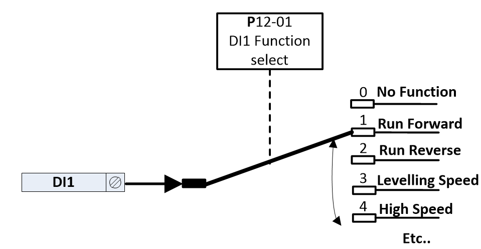 |
The table below shows the available functions which can be assigned to each of the digital inputs.
Setting | Function | Notes | ||||||||||||||||||||||||||||||||||||
|---|---|---|---|---|---|---|---|---|---|---|---|---|---|---|---|---|---|---|---|---|---|---|---|---|---|---|---|---|---|---|---|---|---|---|---|---|---|---|
0 | No Function | |||||||||||||||||||||||||||||||||||||
1 | Run Forward | If both Signals are present at the same time the drive will remain on StoP | ||||||||||||||||||||||||||||||||||||
2 | Run Reverse | |||||||||||||||||||||||||||||||||||||
3 | Levelling Speed (1) | For the drive to run at least 1 input needs to be selected and active, this in addition to a direction command (Run Forward/Run Reverse) and the STO signal being active. | ||||||||||||||||||||||||||||||||||||
4 | High Speed (1) | |||||||||||||||||||||||||||||||||||||
5 | High Speed 5 (1) | |||||||||||||||||||||||||||||||||||||
6 | Inspection Speed (1) | |||||||||||||||||||||||||||||||||||||
7 | Fault Reset | |||||||||||||||||||||||||||||||||||||
8 | Rescue Mode | |||||||||||||||||||||||||||||||||||||
9 | E-Trip Mode 1 | Ok when closed / Thermistor trip if thermistor function selected in P1-09 Analog Input 2 (DI5) Format or motor contactor feedback trip if P3-02 is set to 1 (Enabled) | ||||||||||||||||||||||||||||||||||||
10 | Preset with override High Speed | |||||||||||||||||||||||||||||||||||||
11 | Preset with override Inspection | |||||||||||||||||||||||||||||||||||||
12 | Preset with override Intermediate | |||||||||||||||||||||||||||||||||||||
13 | E-Trip Mode 2 | Ok when closed / E-Trip when open or motor contactor feedback trip if P3-02 is set to 1 (Enabled) | ||||||||||||||||||||||||||||||||||||
14 | Preset Bit 0 (2) | Used for binary selection of speed reference as per below
| ||||||||||||||||||||||||||||||||||||
15 | Preset Bit 1 (2) | |||||||||||||||||||||||||||||||||||||
16 | Preset Bit 2 (2) | |||||||||||||||||||||||||||||||||||||
17 | Speed Reference | |||||||||||||||||||||||||||||||||||||
18 | Torque Sensor | |||||||||||||||||||||||||||||||||||||
19 | Spare | |||||||||||||||||||||||||||||||||||||
20 | Spare | |||||||||||||||||||||||||||||||||||||
21 | Drive Enable | |||||||||||||||||||||||||||||||||||||
22 | E-Trip Mode 3 | Ok when closed / thermistor trip if thermistor function selected in P1-09 Analog Input 2 (DI5) Format | ||||||||||||||||||||||||||||||||||||
23 | Brake Release Monitor Input 1 | |||||||||||||||||||||||||||||||||||||
24 | Brake Release Monitor Input 2 | |||||||||||||||||||||||||||||||||||||
25 | Analog mode | |||||||||||||||||||||||||||||||||||||
26 | Direction (0 – Fwd, 1 - Rev) | |||||||||||||||||||||||||||||||||||||
27 | Preset Bit 0 With Active (3) | For the drive to run at least 1 input needs to be selected and active, this in addition to a direction command and the STO signal being active
| ||||||||||||||||||||||||||||||||||||
28 | Preset Bit 1 With Active (3) | |||||||||||||||||||||||||||||||||||||
29 | Preset Bit 2 With Active (3) |
Parameter Group 12: I/O Configuration example 1
The table below shows an example of a required I/O configuration with Binary Speed Selection
Drive Control Input Terminals | Speed Source | |||||||
|---|---|---|---|---|---|---|---|---|
DI1 | DI2 | DI3 | DI4 | DI5 | DI6 | DI7 | DI8 | |
Open Disabled/ Close Forward | Open Disabled/ Close Reverse | Ok when closed / E-Trip | Fault Reset | Rescue Mode Enable | 0 | 0 | 0 | P8-05 (Levelling Speed) |
1 | 0 | 0 | P8-06 (High Speed) | |||||
0 | 1 | 0 | P8-07 (Intermediate Speed) | |||||
1 | 1 | 0 | P8-08 (Inspection Speed) |
To achieve the above configuration the following group 12 parameters, need to be set.
Parameter number | Parameter Name | Setting | Function |
|---|---|---|---|
P12-01 | DI1 input Function select | 1 | Run Forward |
P12-02 | DI2 input Function select | 2 | Run Reverse |
P12-03 | DI3 input Function select | 13 | E-Trip Mode 2 |
P12-04 | DI4 input Function select | 7 | Fault Reset |
P12-05 | DI5 input Function select | 8 | Rescue Mode |
P12-06 | DI6 input Function select | 14 | Preset Bit 0 |
P12-07 | DI7 input Function select | 15 | Preset Bit 1 |
P12-08 | DI8 input Function select | 16 | Preset Bit 2 |
Parameter Group 12: I/O Configuration example 2
The table below shows an example of a required I/O configuration
Drive Control Input Terminals | |||||||
|---|---|---|---|---|---|---|---|
DI1 | DI2 | DI3 | DI4 | DI5 | DI6 | DI7 | DI8 |
Open Disabled/ Close Forward | Open Disabled/ Close Reverse | Open Disabled/ Levelling Speed (P8-05) | Open Disabled/ Inspection Speed (P8-08) | Open Disabled/ High Speed (P8-06) | Ok when closed / E-Trip when open | Fault Reset | Rescue Mode Enable |
Parameter number | Parameter Name | Setting | Function |
|---|---|---|---|
P12-01 | DI1 input Function select | 1 | Run Forward |
P12-02 | DI2 input Function select | 2 | Run Reverse |
P12-03 | DI3 input Function select | 3 | Levelling Speed |
P12-04 | DI4 input Function select | 6 | Inspection Speed |
P12-05 | DI5 input Function select | 4 | High Speed |
P12-06 | DI6 input Function select | 13 | E-Trip Mode 2 |
P12-07 | DI7 input Function select | 7 | Fault Reset |
P12-08 | DI8 input Function select | 8 | Rescue Mode |
Parameter number | Parameter Name | Minimum | Maximum | Factory Default | Units | Visibility Modes | Accessibility |
|---|---|---|---|---|---|---|---|
P12-01 | DI1 input Function select | 0 | 29 | 1 | - | - | R/W |
P12-02 | DI2 input Function select | 0 | 29 | 2 | - | - | R/W |
P12-03 | DI3 input Function select | 0 | 29 | 3 | - | - | R/W |
P12-04 | DI4 input Function select | 0 | 29 | 4 | - | - | R/W |
P12-05 | DI5 input Function select | 0 | 29 | 5 | - | - | R/W |
P12-06 | DI6 input Function select | 0 | 29 | 6 | - | - | R/W |
P12-07 | DI7 input Function select | 0 | 29 | 7 | - | - | R/W |
P12-08 | DI8 input Function select | 0 | 29 | 8 | - | - | R/W |
P12-09 | Daux1 input Function select | 0 | 29 | 0 | - | - | R/W |
P12-10 | Daux2 input Function select | 0 | 29 | 0 | - | - | R/W |
P12-11 | Speed Reference Source | 0 | 5 | 0 | - | - | R/W |
P12-12 | Reference Active | 0 | 1 | 0 | - | - | R/O |
P12-13 | User pre-ramp reference | -1500.00 | 1500.00 | 0 | rpm | - | R/O |
Note that whenever P1-02 (Digital Input Function Select) is changed parameter group 12 is automatically updated to reflect the new terminal assignments.
Parameter Group 0 – Monitoring Parameters
Parameter Number | Parameter Description | Units | ||||||||||||||||||||||||||||||||||||||||||||||||||||||
|---|---|---|---|---|---|---|---|---|---|---|---|---|---|---|---|---|---|---|---|---|---|---|---|---|---|---|---|---|---|---|---|---|---|---|---|---|---|---|---|---|---|---|---|---|---|---|---|---|---|---|---|---|---|---|---|---|
P0-00 | Keypad Parameter Display Mode | |||||||||||||||||||||||||||||||||||||||||||||||||||||||
This parameter allows the user to see only the parameters that have been set different to defaults. 0 = Show all Parameters (Taking into account Level access code) 1 = Show Only parameters that are different from Factory defaults. 2 = Show Only parameters that are different from User defaults. | ||||||||||||||||||||||||||||||||||||||||||||||||||||||||
P0-01 | Digital Input 1 to 5 Status | - | ||||||||||||||||||||||||||||||||||||||||||||||||||||||
Displays the status of the drive digital inputs 1 to 5
1 = Input Active 0 = Input InActive | ||||||||||||||||||||||||||||||||||||||||||||||||||||||||
P0-02 | Digital Input 6 to 10 Status | - | ||||||||||||||||||||||||||||||||||||||||||||||||||||||
Displays the status of the drive digital inputs 6 to 8 and Auxiliary inputs within encoder module
*Daux are the auxiliary inputs on the encoder module 1 = Input Active 0 = Input InActive | ||||||||||||||||||||||||||||||||||||||||||||||||||||||||
P0-03 | STO Input Status | - | ||||||||||||||||||||||||||||||||||||||||||||||||||||||
Displays the status of the Safe Torque Inputs. Value Displayed:
1 = Input Active 0 = Input InActive | ||||||||||||||||||||||||||||||||||||||||||||||||||||||||
P0-04 | Relay 1 Status | - | ||||||||||||||||||||||||||||||||||||||||||||||||||||||
Displays the status of Relay 1
0 = Relay Open 1 = Relay Closed | ||||||||||||||||||||||||||||||||||||||||||||||||||||||||
P0-05 | Relay 2 Status | - | ||||||||||||||||||||||||||||||||||||||||||||||||||||||
Displays the status of Relay 2
0 = Relay Open 1 = Relay Closed | ||||||||||||||||||||||||||||||||||||||||||||||||||||||||
P0-06 | Digital Output Status | - | ||||||||||||||||||||||||||||||||||||||||||||||||||||||
Displays the status of the drive digital Outputs
0 = Digital Output InActive 1 = Digital Output Active | ||||||||||||||||||||||||||||||||||||||||||||||||||||||||
Parameter Number | Parameter Description | Units | ||||||||||||||||||||||||||||||||||||||||||||||||||||||
P0-07 | Analog Output 1 Value | 0.0V – 10.0V (Voltage Mode)
(Current mode) | ||||||||||||||||||||||||||||||||||||||||||||||||||||||
Shows the voltage/Current output value from Analog output 1 after scaling and offsets have been applied.
| ||||||||||||||||||||||||||||||||||||||||||||||||||||||||
P0-08 | Analog Output 2 Value | 0.0V – 10.0V (Voltage Mode)
(Current mode) | ||||||||||||||||||||||||||||||||||||||||||||||||||||||
Shows the voltage/Current output value from Analog output 2 after scaling and offsets have been applied.
| ||||||||||||||||||||||||||||||||||||||||||||||||||||||||
P0-09 | Motor contactor measured opening time | |||||||||||||||||||||||||||||||||||||||||||||||||||||||
P0-10 | Motor contactor measured Closing time | |||||||||||||||||||||||||||||||||||||||||||||||||||||||
P0-11 | Brake Release measured opening time | |||||||||||||||||||||||||||||||||||||||||||||||||||||||
P0-12 | Brake Apply measured Closing time | |||||||||||||||||||||||||||||||||||||||||||||||||||||||
P0-13 | Pre-Ramp Speed Controller Reference | Hz/RPM/Linear | ||||||||||||||||||||||||||||||||||||||||||||||||||||||
Displays the set point reference input applied to the drive internal speed controller | ||||||||||||||||||||||||||||||||||||||||||||||||||||||||
P0-14 | Speed Reference via Fieldbus Network | Hz/RPM/Linear | ||||||||||||||||||||||||||||||||||||||||||||||||||||||
Displays the setpoint being received by the drive from the currently active Fieldbus interface. | ||||||||||||||||||||||||||||||||||||||||||||||||||||||||
P0-15 | Post-Ramp Speed Controller Reference | Hz/RPM/Linear | ||||||||||||||||||||||||||||||||||||||||||||||||||||||
Displays the post-ramp set-point reference applied to the drive internal speed controller | ||||||||||||||||||||||||||||||||||||||||||||||||||||||||
P0-16 | Speed Error | Hz/RPM/Linear | ||||||||||||||||||||||||||||||||||||||||||||||||||||||
Speed Error between the post-ramp speed reference (P0-15) and.. Rotor speed (P0-18) with Encoder disabled Encoder speed (P0-19) with Encoder Enabled. | ||||||||||||||||||||||||||||||||||||||||||||||||||||||||
P0-17 | Rollback Error | Pulses | ||||||||||||||||||||||||||||||||||||||||||||||||||||||
Displays the rollback count | ||||||||||||||||||||||||||||||||||||||||||||||||||||||||
P0-18 | Rotor Speed (Estimated or Measured) | Hz/RPM/Linear | ||||||||||||||||||||||||||||||||||||||||||||||||||||||
This parameter displays either the estimated rotor speed of the motor, if no encoder feedback is present, or the measured rotor speed if an optional Encoder Feedback Interface Option is fitted. (64ms moving average) | ||||||||||||||||||||||||||||||||||||||||||||||||||||||||
P0-19 | Encoder Feedback Speed | Hz/RPM/Linear | ||||||||||||||||||||||||||||||||||||||||||||||||||||||
Displays the Actual Encoder Feedback speed. | ||||||||||||||||||||||||||||||||||||||||||||||||||||||||
P0-20 | Real-time Encoder offset Value | ° | ||||||||||||||||||||||||||||||||||||||||||||||||||||||
Live Encoder offset value shown in Degrees (1 degree resolution) | ||||||||||||||||||||||||||||||||||||||||||||||||||||||||
P0-21 | Calculated Slip Speed Value (Enhanced V/F Mode Only) | - | ||||||||||||||||||||||||||||||||||||||||||||||||||||||
P0-22 | Measured Motor Power Factor | |||||||||||||||||||||||||||||||||||||||||||||||||||||||
Real time motor power factor whilst drive is running. | ||||||||||||||||||||||||||||||||||||||||||||||||||||||||
P0-23 | Highest Current During Acceleration | |||||||||||||||||||||||||||||||||||||||||||||||||||||||
P0-24 | Highest Current During Deceleration | |||||||||||||||||||||||||||||||||||||||||||||||||||||||
P0-25 | Motor Current | A | ||||||||||||||||||||||||||||||||||||||||||||||||||||||
Parameter Number | Parameter Description | Units | ||||||||||||||||||||||||||||||||||||||||||||||||||||||
P0-26 | Motor Magnetising Current (Id) | A | ||||||||||||||||||||||||||||||||||||||||||||||||||||||
Displays the motor magnetising Current, providing an auto tune has been successfully completed. | ||||||||||||||||||||||||||||||||||||||||||||||||||||||||
P0-27 | Motor Rotor Current (Iq) | A | ||||||||||||||||||||||||||||||||||||||||||||||||||||||
Displays the motor Rotor (torque producing) current, providing an auto tune has been successfully completed. | ||||||||||||||||||||||||||||||||||||||||||||||||||||||||
P0-28 | Output Torque | % | ||||||||||||||||||||||||||||||||||||||||||||||||||||||
Displays the instantaneous output torque level produced by the motor. 0.1% resolution 100% = motor rated torque. | ||||||||||||||||||||||||||||||||||||||||||||||||||||||||
P0-29 | Motor Input Power | |||||||||||||||||||||||||||||||||||||||||||||||||||||||
P0-30 | Motor Shaft Power | |||||||||||||||||||||||||||||||||||||||||||||||||||||||
P0-31 | Motor Overload Accumulator (%) | % | ||||||||||||||||||||||||||||||||||||||||||||||||||||||
P0-32 | Back EMF Measured Value | |||||||||||||||||||||||||||||||||||||||||||||||||||||||
Ph-Ph back emf measurement | ||||||||||||||||||||||||||||||||||||||||||||||||||||||||
P0-33 | Drive Output Voltage | VAC | ||||||||||||||||||||||||||||||||||||||||||||||||||||||
Displays the instantaneous output voltage from the drive to the motor | ||||||||||||||||||||||||||||||||||||||||||||||||||||||||
P0-34 | Motor Poles Calculated | |||||||||||||||||||||||||||||||||||||||||||||||||||||||
Displays the calculated number of pole pairs when the motor pole parameter (P4-05) is set to 0 (Automatic calculation of motor poles). | ||||||||||||||||||||||||||||||||||||||||||||||||||||||||
P0-35 | Travel Profile Position | |||||||||||||||||||||||||||||||||||||||||||||||||||||||
Displays the current position on the travel curve.
Further Reported States
|
P0-36 | Travel Profile Trip point | |||||||||||||||||||||||||||||||||||||||||||||||||||||||
|---|---|---|---|---|---|---|---|---|---|---|---|---|---|---|---|---|---|---|---|---|---|---|---|---|---|---|---|---|---|---|---|---|---|---|---|---|---|---|---|---|---|---|---|---|---|---|---|---|---|---|---|---|---|---|---|---|
This parameter indicates at what point on the travel curve the drive tripped.
Further Reported States
|
Parameter Number | Parameter Description | Units | ||||||||
|---|---|---|---|---|---|---|---|---|---|---|
P0-37 | Currently active Trip code | |||||||||
This parameter indicates the current trip code. | ||||||||||
P0-38 | Trip History Log | |||||||||
Displays the last four fault codes.
| ||||||||||
P0-39 | Drive Run Time Since Last Trip | HH:MM:SS | ||||||||
Displays the total operating? Or Run time of the drive since the last fault occurred. The first value shown is the number of hours. Pressing the Up key will display the minutes and seconds.
| ||||||||||
P0-40 | DC Bus Voltage | V | ||||||||
Displays the instantaneous DC Bus Voltage internally within the drive | ||||||||||
P0-41 | DC Bus Voltage Ripple | V | ||||||||
Displays the level of ripple present on the DC Bus Voltage. | ||||||||||
P0-42 | L1 Input Voltage | VAC | ||||||||
P0-43 | L2 Input Voltage | VAC | ||||||||
P0-44 | L3 Input Voltage | VAC | ||||||||
P0-45 | Motor Thermistor Resistance | Ω | ||||||||
Analogue Input 1 thermistor | ||||||||||
P0-46 | Motor Thermistor 2 Resistance | Ω | ||||||||
Analogue input 2 thermistor | ||||||||||
P0-47 | Brake Resistor Active | - | ||||||||
0 = Brake Resistor Off 1 = Brake Resistor On | ||||||||||
P0-48 | IGBT Temperature | °C | ||||||||
Displays the Instantaneous Heatsink (IGBT thermistor) Temperature measured by the drive | ||||||||||
P0-49 | Drive Internal Temperature | °C | ||||||||
Displays the Instantaneous Internal (Control PCB) Temperature measured by the drive | ||||||||||
P0-50 | Drive Run Time Since Last Trip | HH:MM | ||||||||
Displays the running time of the drive since the last trip occurred. The first value shown is the number of hours. Pressing the Up key will display the minutes and seconds.
| ||||||||||
P0-51 | Drive Run Time Since Last Trip 2 | HH:MM | ||||||||
Displays the running time of the drive since the 2nd to last trip occurred. The first value shown is the number of hours. Pressing the Up key will display the minutes and seconds.
| ||||||||||
P0-52 | Drive Run Time Since Last Enable | HH | ||||||||
Displays the total running time of the drive since the last Run command was received. The first value shown is the number of hours. Pressing the Up key will display the minutes and seconds.
| ||||||||||
Parameter Number | Parameter Description | Units | ||||||||
P0-53 | Drive Lifetime Operating Time | HH | ||||||||
Displays the total operating time of the drive. The first value shown is the number of hours. Pressing the Up key will display the minutes and seconds.
| ||||||||||
P0-54 | Drive Total Run Time | HH | ||||||||
Displays the total run time of the drive. The first value shown is the number of hours. Pressing the Up key will display the minutes and seconds.
| ||||||||||
P0-55 | Drive Heatsink Cooling Fan Total Operating Time | HH | ||||||||
Displays the total operating time of the drive internal cooling fans. The first value shown is the number of hours. Pressing the Up key will display the minutes and seconds. This is used for scheduled maintenance information
|
Parameter Number | Parameter Description | Units | ||||||||||
|---|---|---|---|---|---|---|---|---|---|---|---|---|
P0-56 | Analog Input 1 Applied Signal Value | V or mA depending on signal format set in P1-03 | ||||||||||
Displays the actual signal level applied to analog input 1 (DI4) before scaling and offsets have been applied. | ||||||||||||
P0-57 | Analog Input 1 Final Signal Value | V or mA depending on signal format set in P1-03 | ||||||||||
Displays the signal level after Offset (P1-04) and Scaling (P1-05) is applied | ||||||||||||
P0-58 | Analog Input 2 Applied Signal Value | V or mA depending on signal format set in P1-09 | ||||||||||
Displays the actual signal level applied to analog input 2 (DI5) before scaling and offsets have been applied. | ||||||||||||
P0-59 | Analog Input 2 Final Signal Value | V or mA depending on signal format set in P1-09 | ||||||||||
Displays the signal level after Offset (P1-10) and Scaling (P1-11) is applied | ||||||||||||
P0-60 | DC Bus Voltage Log | V | ||||||||||
Displays the Last 16 values | ||||||||||||
P0-61 | DC Bus Voltage Ripple Log | V | ||||||||||
P0-62 | Heatsink Temperature Log | °C | ||||||||||
P0-63 | Drive Internal Temperature Log | °C | ||||||||||
P0-64 | Motor Current Log | A | ||||||||||
P0-65 | Motor Speed Log | Hz/RPM/Linear | ||||||||||
The above parameters are used to store the history of various measured levels within the drive at various regular time intervals prior to a trip. The values are frozen when a fault occurs and can be used for diagnostic purposes | ||||||||||||
P0-66 | Encoder Speed Log | Hz/RPM/Linear | ||||||||||
The above parameters are used to store the history of various measured levels within the drive at various regular time intervals prior to a trip. The values are frozen when a fault occurs and can be used for diagnostic purposes | ||||||||||||
P0-70 | Drive Type | - | ||||||||||
Displays the type details of the drive
| ||||||||||||
P0-71 | Option Module Type | - | ||||||||||
Displays the type details of the drive
| ||||||||||||
P0-72 | Drive IO Firmware Version | - | ||||||||||
| ||||||||||||
P0-73 | Drive Power Stage Firmware Version | - | ||||||||||
| ||||||||||||
P0-74 | Drive Serial Number | - | ||||||||||
Displays the unique serial number of the drive.
| ||||||||||||
P0-75 | PS Read Value | - | ||||||||||
? |


