Commissioning an Induction Motor
Note
This guide applies to induction motors only (default motor type).
Before you begin, ensure:
The drive is mechanically and electrically installed.
A Control Source and Speed Reference Source have been configured.
Select the application type (Pump / Fan / General)
P-13 = 0 for General Purpose (default)
P-13 = 1 for Pump
P-13 = 2 for Fan
Note
For pump applications, mode 1 is for use with centrifugal type pumps, for other type of pumps then mode 0 may need to be used.
Select Motor Control Type (P-51)
Choose the control method based on performance needs:
P-51
0 : IM Smart Vector Speed Control
Dynamic response and higher torque at low speed
1 : V/F Speed Control
Default setting suitable for most situations
7 : IM Full Vector Speed Control
More dynamic response and increased torque at low speed
Enter Motor nameplate data
Motor Voltage > P-07.0
Motor Rated Current > P-08
Motor Rated Frequency > P-09
Motor Power Factor > P-50 (IM Full Vector Speed Control only)
Note
Optionally entering the motor nameplate speed in P-10 (Motor Rated Speed) enables slip compensation, allowing the drive to automatically compensate for speed reduction as load is applied to the motor.
Run Autotune (Optional)
P-52 > 1
Note
Performing an Autotune will provide more accurate motor data than the default values, and therefore better performance and optimised motor current.
The drive can now be run from your chosen control source and speed reference.
Voltage Boost (P-11)
Voltage Boost increases the motor voltage at low frequencies, improving starting performance and low-speed torque when operating in V/F Speed Control mode.
When to Increase P-11
Increase P-11 for applications requiring:
Higher starting torque
Improved low-speed performance
Constant torque loads such as conveyors, mixers and positive displacement pumps
Tip
Suitable setting can usually be found by operating the motor under very low or no load conditions at approximately 5Hz, and adjusting P-11 until the motor current is approximately the magnetising current (if known)
Typical values for a size 1 drive is 60-80% and a size 2 drive 50-60%.
Caution
If P-11 is too low → Motor may stall at low speed or during start-up
If P-11 is too high → Drive may trip on over-current faults (O-I or It.trp)
Always verify that motor current remains within the motor's rated current.
Voltage Boost Example
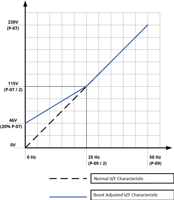
For a typical 230 V, 50 Hz induction motor, increasing P-11 increases the voltage applied at low frequencies.
For example:
P-11 = 20% provides additional voltage boost at low speed.
This can improve motor starting performance and low-speed torque.
The resulting V/F characteristic follows the boosted (blue) curve shown in the diagram
V/Hz Curve Adjustment
V/F Characteristic Adjustment allows the standard voltage-frequency curve to be modified by defining an additional adjustment point.
This can be used to optimise motor performance, improve efficiency, or better match the motor characteristics to the application.
For most applications, the default linear V/F curve is sufficient. However, some applications may benefit from a customised V/F characteristic.
V/F Curve Example for Fan Applications
For a typical 230 V, 50 Hz induction motor:
Parameter | Value |
|---|---|
P-07 | 230 V |
P-09 | 50 Hz |
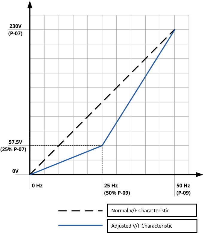
To create a reduced-voltage V/F curve suitable for centrifugal fans:
Parameter | Value |
|---|---|
P-28 (V/F Adjustment Voltage) | 25% of P-07 (57.5 V) |
P-29 (V/F Adjustment Frequency) | 50% of P-09 (25 Hz) |
The resultant V/F curve is shown below:
Tip
Lower voltage at low speeds can significantly reduce energy consumption in centrifugal fan and pump applications while maintaining the required load performance.
Question | Solution/Answer |
|---|---|
Do the other boost parameters P-11.1, P-11.2, P-11.3, P-11.4 have any effect ? | Yes |
What happens if I run an autotune ? | Parameters P-55.0, P-55.1, P-56.0, P-56.1 and P-57 are populated, this provides more accurate motor data than the default values, and therefore better performance and optimised motor current. |
Note
IM Smart Vector Speed Control provides higher motor performance than standard V/F control, including improved speed regulation, torque response, and load handling.
Select the Motor Control Mode
Set P-51 (Motor Control Type) = 0 to enable IM Smart Vector control.
Enter Motor Nameplate Data
Parameter
Description
P-07
Motor Rated Voltage
P-08
Motor Rated Current
P-09
Motor Rated Frequency
P-50
Motor Power Factor
Note
Optionally entering the motor nameplate speed in P-10 (Motor Rated Speed) enables slip compensation, allowing the drive to automatically compensate for speed reduction as load is applied to the motor.
Run an Autotune
Set P-52 = 1 to start an autotune.
During the autotune, the display will show "Auto-t" while the drive measures the motor's electrical characteristics.
Note
Note: The autotune is a stationary test. The motor shaft does not rotate during the measurement.
The drive can now be run from your chosen control source and speed reference.
Question | Solution |
|---|---|
What happens if I run an autotune ? | Parameters P-55.0, P-55.1, P-56.0, P-56.1 and P-57 are populated, this provides more accurate motor data than the default values, and therefore better performance and optimised motor current. |
Note
IM Smart Vector Speed Control provides higher motor performance than standard V/F control, including improved speed regulation, torque response, and load handling.
Select the Motor Control Mode
Set P-51 (Motor Control Type) = 7 to enable IM Full Vector Speed Control.
Enter Motor Nameplate Data
Parameter
Description
P-07
Motor Rated Voltage
P-08
Motor rated Voltage
P-09
Motor rated Current
P-50
Motor Power Factor
Note
Optionally entering the motor nameplate speed in P-10 (Motor Rated Speed) enables slip compensation, allowing the drive to automatically compensate for speed reduction as load is applied to the motor.
Run an Autotune
Set P-52 = 1 to start an autotune.
During the autotune, the display will show "Auto-t" while the drive measures the motor's electrical characteristics.
Note
Note: The autotune is a stationary test. The motor shaft does not rotate during the measurement.
The drive can now be run from your chosen control source and speed reference.
Question | Solution |
|---|---|