Speed References
To control the motor speed using a Voltage signal, the signal must be connected to one of the 2 available Analog inputs as shown below, alternatively a Potentiometer can be used.
Before Starting
Ensure the motor data parameters have been entered.
The below guidance assumes all other parameters are in a default state.
The motor will not run until a start command signal has been given to the drive, e.g. connect a switch between terminal 1 and terminal 2, "See how to start the motor TBC"
Note
Analog Input 1 (DA4) or 2 (DA3) can be used to control motor speed.
As shown below the control voltage signal can come from either an external voltage source or the drives on-board voltage source via a Potentiometer.
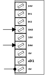
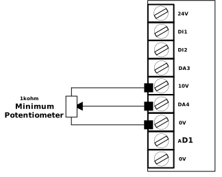
For Analog Input 1 (DA4) Connect the voltage signal source to the drive terminals :
Signal (+) → Terminal (DA4) & Signal (0V / GND) → Terminal 0V
For Analog Input 2 (DA3) Connect the voltage signal source to the drive terminals :
Signal (+) → Terminal (DA3) & Signal (0V / GND) → Terminal 0V
If using a potentiometer using Analog Input 1 (DA4) :
+10 V supply → potentiometer high, 0 V → potentiometer low, Wiper output → DA4
If using a potentiometer using Analog Input 2 (DA3) :
+10 V supply → potentiometer high, 0 V → potentiometer low, Wiper output → DA3
Tip
From Default a 0Vdc signal at terminal DA4 will result in the motor speed running at 0Hz and a 10Vdc signal will result in the motor running at maximum speed (as per set in P-01).
From defaults a 0Vdc Signal will result in the motor running at zero speed and 10Vdc will result in the motor running at Maximum speed (e.g. 50Hz), but what if you want for example 2 V → 0 Hz & 10 V → 40 Hz.
The table and diagram below shows examples of how the scaling and offset parameters can be used to achieve the application required minimum and maximum output speed from different voltage ranges.
Voltage Signal | Resultant Output Speed | Analog Input Format DA3 (Anip2) P-47.0 DA4 (Anip 1) P-16.0 | Analog Input Low Voltage DA3 (Anip2) P-58.0 DA4 (Anip 1) P-35 | Analog Input Maximum Voltage DA3 (Anip2) P-58.1 DA4 (Anip 1) P-35.1 | Analog Input Low Speed reference DA3 (Anip2) P-58.2 DA4 (Anip 1) P-35.2 | Analog Input Maximum Speed reference DA3 (Anip2) P-58.3 DA4 (Anip 1) P-35.3 |
|---|---|---|---|---|---|---|
0-10Vdc | 0V = 0Hz 10V = 50Hz | U 0-10 | 0.0 | 10.0 | 0.00 | 50.00 |
2-8Vdc | 2V = 0Hz 8V = 40Hz | U ScAL | 2.0 | 8.0 | 0.00 | 40.00 |
Tip
If you want the motor speed to increase as the Voltage signal increases then set P-16.1 to 0
If you want the motor speed to decrease as the Voltage signal increases then set P-16.1 to 1
Problem | Solution/Answer |
|---|---|
Drive isn't running at expected speed using 0-10V signal | Ensure all inputs are inactive, other than DI1 as the run signal, and the AI signal. |
How can I confirm that the drive is seeing the voltage signal ? | For Analog input 1 (Terminal DA4) the applied voltage can be viewed in Parameter P0-09. For Analog input 2 (Terminal DA3) the applied voltage can be viewed in Parameter P0-11. |
What Happens if I set a Minimum speed value in P-02 | The full range of Analog input voltage will be effective between the Minimum Speed and Maximum speed |