Master Follower Operation
Overview
The Master-Follower function allows multiple drives to operate together from a single speed reference and run command.
Up to 63 drives can be connected using the built-in RJ45 communication ports. One drive is configured as the Master, while all remaining drives are configured as Followers. The Master transmits its run status and output frequency to all connected follower drives.
Follower drives can also be configured with speed scaling or trim functions to maintain a fixed speed ratio or speed offset relative to the Master.
Before You Begin
Ensure all drives have been commissioned correctly.
Verify motor data parameters have been entered.
Ensure all drives are operating with default settings unless otherwise required.
Verify each drive has a valid enable signal available (for example, DI1).
Ensure the required RJ45 cables and splitters are available.
Note
The Motor will not run until a valid start command is applied to the drive.
Networking the drives together
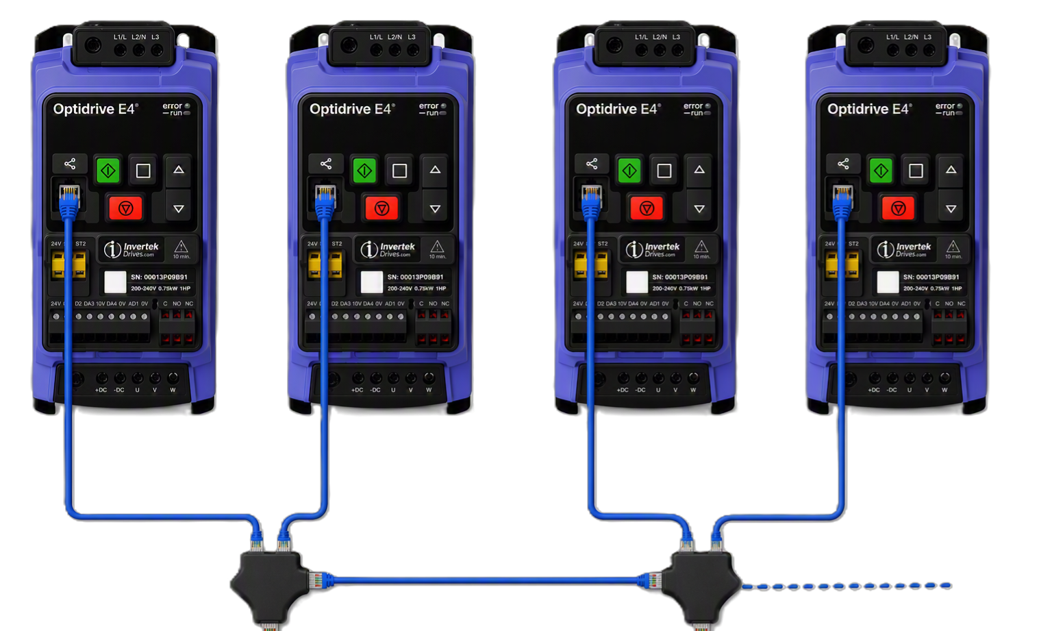
The below is an example of the wiring required.
Remove power from all drives.
Connect the RJ45 communication ports using the required RJ45 leads and splitters.
Reapply power to all drives.
Configure Master-Follower Operation
Step 1 - Configure the Master Drive
Connect the required external control signals to the Master drive.
Set P-67.0 = 1 to enable Master operation.
Set P-67.1 = Obus (1).
Configure the required speed reference and operating mode.
Verify the drive can start and stop correctly before connecting any follower drives.
Step 2 - Configure the Follower Drives
Set P-67.0 = 2.
Set P-12 = 7 (Follower Mode).
Set P-67.1 = Obus (1).
Apply an enable signal to the drive.
Note
Configure each additional drive in the same manner but using a unique address in P-67.0 e.g. 3, 4, 5...
For identical speed tracking, it is recommended to:
Use the same acceleration (P-03) and deceleration (P-04) ramps on all drives.
Leave the follower minimum speed set to 0 Hz unless a different limit is required.
Apply a run command to the Master drive.
Confirm the Master drive starts correctly.
Verify all follower drives start automatically.
Note
Follower Drives need a start signal (for example, DI1).
Adjust the Master speed reference.
Confirm all follower drives track the Master speed.
Stop the Master drive and verify all followers stop correctly.
Notice
Minimum and Maximum Speeds
The follower drive operating speed will always be limited by the programmed Minimum and Maximum Speeds. This means that if the Minimum Speed programmed in the follower drive is greater than the Minimum Speed programmed in the Master drive, the follower speed will not follow the Master Speed once operating below the follower drive minimum speed. In general, where it is intended for the follower drive to operate at the same frequency as the Master drive, the minimum speed can simply be left at zero in the follower drive, and the Slave will then follow the Master drive Minimum Speed.
Acceleration and Deceleration Ramp times
During Acceleration and Deceleration, the follower drive operation will be limited by it’s own internal ramp times, whilst following the Master drive. This means that if the ramp times in the follower(s) are longer than those in the Master, the follower speed will briefly lag behind the Master.
Master Follower Operation Notes
All follower drives require an enable signal, e.g. Digital Input 1 (DI1) must be closed in order for the follower to operate. This means that individual follower drives can be disabled if required by switching off Digital Input 1. If Digital Input 1 opens during operation, the follower drive will ramp to standstill at the rate set in P-04, hence this parameter should be set to a suitable value to ensure correct Master follower operation, but still allowing adequate stopping time to prevent any nuisance trips.
Master follower operation can be used in conjunction with other drive functions (e.g. Dynamic braking can be used on all Follower drives).
Where a small speed offset is required between machines, a trim potentiometer can be connected to the Follower drive.
For example, if the Master drive is operating at 20 Hz and a ±2 Hz trim range is configured, the Follower speed can be adjusted between 18 Hz and 22 Hz.
Configuration
Connect the external control circuit or enable signal to the Master drive.
Set P-36.0 = 1 on the Master drive only.
On the Follower drive:
Set a unique follower address in P-36.0 (for example, 2).
Select Follower Mode by setting P-12 = 7.
Ensure the acceleration (P-03) and deceleration (P-04) ramp times are set equal to, or less than, those of the Master drive.
Connect the trim potentiometer to terminals 10V, DA4 and 0V of the Follower drive.
Connect the drives using RJ45 patch cables and RJ45 splitters.
Setting the Trim Range
For bipolar speed adjustment (e.g. ±2 Hz):
Set P-16.0 = 0 to 10 Volts
Calculate P-35.4 as:
P-35.4 = (Trim Bandwidth ÷ P-01) × 100
Example:
Maximum frequency (P-01) = 80 Hz
Required trim range = ±5 Hz
Trim bandwidth = 10 Hz P-35 = (10 ÷ 80) × 100 = 12.5%
Set P-35.4 = 12.5%.
Problem | Solution |
|---|---|
| |