PI Operation
Before Starting
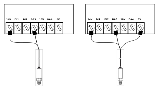
Connect the necessary feedback signals to the drive. e.g. pressure transducer.
Note
Example above shows connection of a 2-wire or loop Powered Transducer (Left) and a 3 or 4 Wire Transducer (Right)
Ensure the motor is commissioned.
Programming
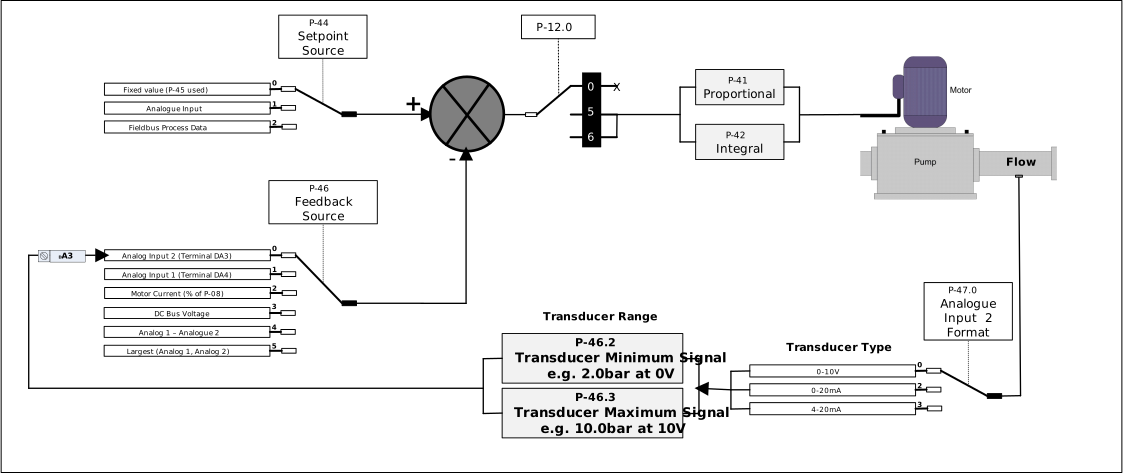
Enable PI Control Mode by Setting parameter P-12.0 to 5
Enter the Feedback Transducer type in parameter P-47.0 e.g. 0-10V
Enter the Feedback Transducer Minimum signal in parameter P-46.2 e.g 2.0 bar when at 0V
Enter the Feedback Transducer Maximum signal in parameter P-46.3 e.g 10.0 bar when at 0V
Define the PI reference Setpoint source in parameter P-44
Once a start signal is provided the drive will run in PI mode.
Define if the system is Direct Operation or Inverse Operation in parameter P-46.1 (see note below)
Note
P-46.1 = 0 Direct Operation, the motor speed will increase when the measured value from the feedback drops
P-46.1 = 1 Inverse Operation, the motor speed will decrease when the measured value from the feedback drops.
Once the values in parameters P46.2 and P46.3 have been entered all set point and feedback values are in real units to match the connected sensor e.g. Bar
Note
Example setup for maintaining pressure in a pumping system, where the Setpoint is a fixed value and the feedback is a 0-10V pressure transducer connected to terminal DA3 (Analog input 2) .
Tuning
Parameter P-41 and P-42 can be used to fine tune the system performance.
Tuning P-41 (Proportional Gain)
Function: This parameter determines how much the drive's output frequency changes in response to small changes in the feedback signal.
Stability Impact: Higher values make the drive more sensitive and responsive to errors. However, setting this value too high can cause system instability and oscillation.
Tuning Strategy: Start with the default value of 1.0. If the system is too slow to reach the set point, increase the value incrementally. If the motor begins to hunt or oscillate rapidly around the target, decrease the value to restore stability.
Tuning P-42 (Integral Time)
Function: This parameter determines how the controller accounts for errors over time to reach the exact set point.
Stability Impact: Larger values provide a more damped response, which is essential for systems where the overall process (such as a large tank filling or a slow-moving temperature change) responds slowly
Tuning Strategy: Start with the default value of 1.0s. If the system overshoots the target or is unstable, increase the integral time to slow down the corrective action and stabilize the process
Standby Mode
For standby set parameter P-48.0 to the time (e.g. 20.0s) where the drive will go to standby (motor will stop) after running at a speed below that set in P48.1.
For Wake Up Level set P-49 to the percentage of pressure drop required to restart the pump (e.g. 5.0%).
Note
The drive will remain in standby until the PI Error (the difference between your target set point and the actual feedback) exceeds the percentage value set in P-49, then the drive automatically restart the motor to reach the set point again.
Parameter | Sub-Index | Description | Minimum | Maximum | Default | Units | ||||||||||||||
|---|---|---|---|---|---|---|---|---|---|---|---|---|---|---|---|---|---|---|---|---|
P-41 | - | PI Controller Proportional Gain | 0.0 | 30.0 | 1.0 | - | ||||||||||||||
P-42 | - | PI Controller Integral Time | 0.0 | 30.0 | 1.0 | s | ||||||||||||||
P-43 | P-43.0 | PI Operation
| 0 | 1 | 0 | - | ||||||||||||||
P-43.1 | PI Mode
| 0 | 1 | 0 | - | |||||||||||||||
P-43.2 | PI Wake Mode Defines if the PI output starts at minimum or maximum on waking from standby. NoteFunction only works if value set in P-49 is greater than 0.0
| 0 | 1 | 0 | - | |||||||||||||||
P-44 | - | PI Reference (Setpoint) Source Select
| 0 | 2 | 0 | - | ||||||||||||||
P-45 | - | PI Fixed Reference | P-46.2 | P-46.3 | 0.0 | Real Units based on setting of P-46.2 and P-46.3 | ||||||||||||||
P-46 | P-46.0 | PI Feedback Source
| 0 | 5 | 0 | - | ||||||||||||||
P-46.1 | PI Feedback Function
| 0 | 1 | 0 | - | |||||||||||||||
P-46.2 | PI Feedback Sensor Minimum Signal | -65535 | 65535 | 0 | - | |||||||||||||||
P-46.3 | PI Feedback Sensor Maximum Signal | -65535 | 65535 | 0 | - | |||||||||||||||
P-48 | P-48.0 | Standby Delay | 0.0 | 250.0 | 0.0 | S | ||||||||||||||
P-48.1 | Standby activation speed | 0.0 | 50.0 | 0.0 | Hz/RPM | |||||||||||||||
P-49 | - | PI Wake Up Error Level | 0.0 | 100.0 | 5.0 | % |
Parameter | Sub-Index | Description |
|---|---|---|
P0-17 Read Only | P0-17.0 | PI Reference Displays the PI reference value in real units |
P0-17.1 | PI Feedback Displays the PI feedback value in real units | |
P0-17.2 | PI Output |
Problem | Solution |
|---|---|
How do I know when the drive is in standby mode? | When the drive enters standby state, the drive output to the motor is disabled, and the display shows the message "stndby". |
Drive is not going into Standby? | Check P-48 is >0 |
|