Electromagnetic Compatibility (EMC)
Recommended Installation for EMC Compliance
All equipment installed within the UK or European Union must comply with the applicable UK or European EMC Directive. The installer must be familiar with the Directive and appropriate good EMC practice. Invertek Drives Ltd products may be considered as a Basic Drive Module or Complete Drive Module according to the EMC standard definition dependent on the drive type. The BDM or CDM may then be incorporated into a Power Drive System. It is the sole responsibility of the installer to ensure that the complete PDS is compliant with the Directive.
Recommended Installation for EMC Compliance
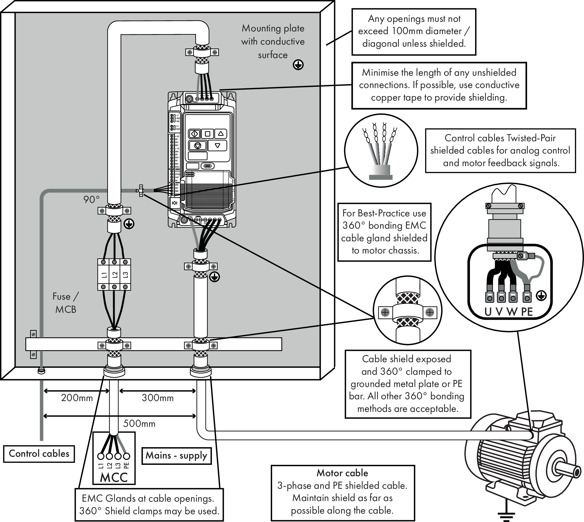
The diagram below provides general guidance to ensure compliance is achieved.
Recommended Installation for EMC compliance |
|---|
 |
Maximum Motor Cable Length to Achieve (m) | ||
|---|---|---|
C1 1,2,4,5,7 | C23,4,5,7 | C36,7 |
1 | 5 | 25 |
General
1Compliance with category C1 conducted emissions only is achieved.
Supply Cable
2A screened (shielded) cable suitable for fixed installation with the relevant mains voltage in use. Braided or twisted type screened cable where the screen covers at least 85% of the cable surface area, designed with low impedance to HF signals. Installation of a standard cable within a suitable steel or copper tube is also acceptable - in this case, ensure that metal tube is adequately grounded.
3A cable suitable for fixed installation with relevant mains voltage with a concentric protection wire. Installation of a standard cable within a suitable steel or copper tube is also acceptable.
Motor Cable
4A screened (shielded) cable suitable for fixed installation with the relevant voltage in use. Braided or twisted type screened cable where the screen covers at least 85% of the cable surface area, designed with low impedance to HF signals.
5The cable shield should be terminated at the motor end using an EMC type gland allowing connection to the motor body through the largest possible surface area. The shield must also be terminated at the drive end, as close as practically possible to the drive output terminals. Where drives are mounted in a steel control panel enclosure, the cable screen may be terminated directly to the control panel backplate using a suitable EMC clamp or gland fitted as close to the drive as possible. The drive earth terminal must also be connected directly to this point, using a suitable cable which provides low impedance to high frequency currents.
Electrical Installation
6A cable suitable for fixed installation with relevant voltage with a concentric protection wire. Installation of a standard cable within a suitable steel or copper tube is also acceptable.
Control Cable
7A shielded cable with low impedance shield. Double shielded twisted pair cable should be used for analog signals.
To completely disconnect the internal filter you must remove both screws at the top and bottom of the drive marked EMC.
Make sure these screws are completely removed and are not just loose.
This should only be carried out where necessary, for example in cases such as IT or ungrounded supplies, where the phase to ground voltage can exceed the phase to phase voltage