Installation Technical Ratings
Drive Ratings
The information provided in the following sections must be adhered to, operating the drive outside of the limits set out could result in incorrect operation of the drive and/or damage to the drive/connected equipment.
200 – 240V +/- 10% - 1 Phase Input / 3 Phase Output - (50/60Hz +/- 5%)
Model Code | Power Rating | Frame Size | Input Current (A) | J Type Fuse | Maximum Supply/Motor Cable Size | Rated Output Current (A) | Recommended Brake Resistance (Ω) (Minimum) | *Brake Resistor power rating (W) | ||
|---|---|---|---|---|---|---|---|---|---|---|
kW | HP | UL (A) | mm2 | AWG/ kcmil | ||||||
ODL-3-220105-142SB# | 2.2 | 3 | 2 | 22 | 25 | 6 | 10 | 10.5 | 35 (20) | 1000 |
200 – 240V +/- 10% - 3 Phase Input / 3 Phase Output - (50/60Hz +/- 5%)
Model Code | Power Rating | Frame Size | Input Current (A) | J Type Fuse | Maximum Supply/Motor Cable Size | Rated Output Current (A) | Recommended Brake Resistance (Ω) (Minimum) | *Brake Resistor power rating (W) | ||
|---|---|---|---|---|---|---|---|---|---|---|
kW | HP | UL (A) | mm2 | AWG/ kcmil | ||||||
ODL-3-220180-342SB# | 4 | 5 | 2 | 22 | 25 | 6 | 10 | 18 | 20 (20) | 1000 |
ODL-3-220240-342SB# | 5.5 | 7.5 | 2 | 27 | 40 | 6 | 10 | 24 | 20 (20) | 1500 |
ODL-3-320300-342SB# | 7.5 | 10.0 | 3 | 34 | 40 | 16 | 6 | 30 | 20 (12) | 2000 |
ODL-3-420460-342SB# | 11 | 15 | 4 | 60 | 70 | 35 | 2 | 46 | 28 (22) | 3000 |
ODL-3-420610-342SB# | 15 | 20 | 4 | 78 | 90 | 35 | 2 | 61 | 28 (22) | 4000 |
ODL-3-420720-342SB# | 18.5 | 25 | 4 | 66 | 90 | 35 | 2 | 72 | 28 (22) | 4500 |
380 – 480 Volt +/-10% - 3 Phase Input / 3 Phase Output - (50-60Hz +/- 5%)
Model Code | Power Rating | Frame Size | Input Current (A) | J Type Fuse | Maximum Supply/Motor Cable Size | Rated Output Current (A) | Recommended Brake Resistance (Ω) (Minimum) | *Brake Resistor power rating (W) | ||
|---|---|---|---|---|---|---|---|---|---|---|
kW | HP | UL (A) | mm2 | AWG/ kcmil | ||||||
ODL-3-240095-342SB# | 4 | 5 | 2 | 14 | 20 | 6 | 10 | 9.5 | 100 (40) | 1000 |
ODL-3-240140-342SB# | 5.5 | 7.5 | 2 | 21 | 25 | 6 | 10 | 14 | 75 (40) | 1500 |
ODL-3-340180-342SB# | 7.5 | 10 | 3 | 24 | 30 | 16 | 6 | 18 | 50 (22) | 2000 |
ODL-3-340240-342SB# | 11 | 15 | 3 | 30 | 40 | 16 | 6 | 24 | 40 (22) | 3000 |
ODL-3-340300-342SB# | 15 | 20 | 3 | 38 | 40 | 16 | 6 | 30 | 50 (22) | 4000 |
ODL-3-440390-342SB# | 18.5 | 25 | 4 | 46 | 50 | 35 | 2 | 39 | 28 (22) | 4500 |
ODL-3-440460-342SB# | 22 | 30 | 4 | 55 | 60 | 35 | 2 | 46 | 28 (22) | 5000 |
NOTE:
*The Resistor power rating shown are guideline only, the values should be calculated based on the individual application, considering the braking power and duty cycle of the elevator. |
Drive Dimensions
Drive Dimensions and Weights
Drive Frame Size | Height (h.) | Width (w.) | Depth (d.) | Weight | |||||
|---|---|---|---|---|---|---|---|---|---|
Units | mm | in | mm | in | mm | in | kg | lb | |
2 | 220 | 8.66 | 110 | 4.33 | 184 | 7.24 | 1.8 | 4.0 | 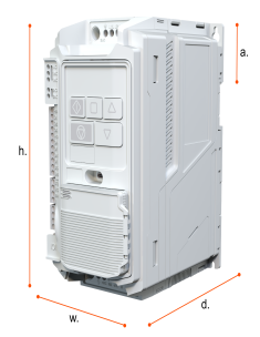 |
3 | 261 | 10.39 | 131 | 5.16 | 207 | 8.15 | 3.5 | 7.7 | |
4 | 418 | 16.46 | 172 | 6.77 | 254 | 10 | 10.36 | 22.9 | |
Note
Drive dimensions include the optional Universal Encoder Module but not the optional Cable Management Bracket.
Using the Foot Mounting points
When referring to Mounting Points in the documentation it means the holes where the drive can be panel mounted.
The screw size for the drive mounting points are shown in the table below.
All four mounting points should be used to install the drive.
Drive Size | Mounting Points | Mounting Bolts | |||||
|---|---|---|---|---|---|---|---|
e | f | Metric | UNF | ||||
mm | in | mm | in | ||||
2 | 210 | 8.27 | 93 | 3.66 | M5 | #10 | 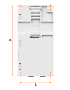 |
3 | 250 | 9.84 | 113 | 4.45 | M5 | #10 | |
4 | 399 | 15.7 | 125 | 4.92 | M6 | 1/4 | |
For the best cooling the drive requires the following clearances:
Drive Size | Vertical Clearance (X) | Horizontal Clearance (Y) | |||
|---|---|---|---|---|---|
mm | in | mm | in | ||
2 | 75 | 2.95 | 50 | 1.97 | 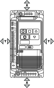 |
3 | 100 | 3.94 | 50 | 1.97 | |
4 | 200 | 7.87 | 10 | 0.39 | |
Environmental Data
To prolong the life of the Drive, it should be installed in an environment that satisfies the following constraints:
Environment Factor to be Considered | Condition to be adhered to |
|---|---|
Location of Installation | Indoors |
Ambient Temperature | -10°C ... 50°C @10 kHz No Derating required |
Storage Temperature | -40°C ... 60°C |
Humidity | <95% (non-condensing) |
Altitude | Maximum altitude with no derating:- 1000m Maximum approved UL installation:- 2000m / 6562ft with derating Maximum non-UL approved installation:- 4000m with derating |
Drive Mounting | The drive must be mounted vertically with enough surrounding area to allow proper cooling and prevent temperature related trips |
Drive Mounting Position | The drive must be mounted vertically. |
Note
For more information on compliant UL installation please see the section from the Quick Start Manual.