Gearless Open Loop Commissioning
The Elevator Core drive can control Gearless Permanent Magnet Motors in Open Loop (No Encoder Feedback) in specific situations.
Operating Gearless Permanent Magnet Motors with no encoder feedback should only be used for the following:
Commissioning for closed loop operation:
Reading the Real-time encoder offset
Checking motor phase orientation
Checking encoder channel direction
Encoder fault diagnosing:
If an encoder wire break has happened detect which channel is broken
Problem with the Universal Encoder Module so get passengers to the next floor
Gearless Open Loop Commissioning - Guide
The below procedure illustrates a method for commissioning the drive in a typical elevator application.
If you have already commissioned the drive for Gearless Permanent Magnet Motor operation in closed loop disregard Steps 1 - 5 and go straight to Step 6.
Step 1 - Wiring Connections
It is assumed the drive is connected as per Overall Wiring Diagram section and default terminal functions.
Step 2- Pre-Power Checks
Action/Checks | Additional Information | |
|---|---|---|
 Do Not Apply Electrical Power Yet! |
| |
Check all necessary electrical connections. |
| |
Step 3 - Applying Power
 Apply Electrical Power to the drive |
|
|
Step 4 - Motor Nameplate Data Entry
Action | Additional Information | |
|---|---|---|
Select Gearless (Permanent Magnet) motor control mode. (P4-01) |
| Both IPM and SPM type motors are supported. |
Enter Motor Back EMF (P4-02) |
| Obtained from motor nameplate or datasheet. If not available can be calculated/measured with the following options:
|
Enter Motor Rated Current (P4-03) |
| Obtained from Motor nameplate (Amps). |
Enter Motor Rated Frequency (P4-04) |
| Obtained from Motor nameplate (Hz). |
Enter Number of Motor Poles (P4-05) |
| Enter motor pole value as shown on the motor nameplate, if unknown set P4-05 to 0 where the drive will automatically calculate the value providing P4-04 (Motor Rated Frequency) and P4-06 (Motor rated speed) have been entered correctly. |
Enter Motor Rated Speed (P4-06) |
| Obtained from Motor nameplate. If not available it can be calculated: Motor Rated Frequency*120/motor poles. |
Enter the Maximum Speed (P8-01) |
| This is the maximum allowable speed. |
Step 5 - Motor Auto-tune
A Motor Auto-tune must be carried out in order to measure the motor electrical characteristics, brakes will be applied by the drive (unless controlled by other means) during this test.
Action | Additional Information | |
|---|---|---|
NOTE: For the motor contactor to close the safety chain will need to be closed. | ||
| 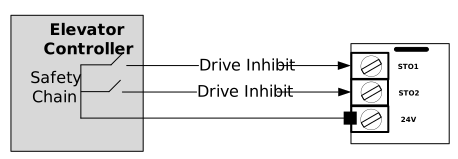 | Drive should now show Stop if not see Troubleshooting. The STO input status can be viewed in parameter P0-03 (0 = Open 1 = Closed) |
| Set P4-08 to a 1 and press |
Once the Auto-tune has been completed P4-08 will return to 0 and the display will show Stop (parameters P4-24, P4-26, P4-27 and P4-30 should change values from their defaults). NOTE: Motor Auto-tune will need to be repeated if the motor, motor cables, motor parameters or drive control mode is changed in P4-01. |

Step 6 - Open Loop Drive Setup
When running a Gearless Permanent Magnet Motor in open loop there is no feedback to align the poles at start. So boost must be provided to run the drive.
Action | Additional Information | |
|---|---|---|
Set low frequency boost |
| These parameters provided extra boost to help with motor control. A general run on setting is start at 10% and if that is not enough increase in increments of 10%. |
Disabling the Encoder |
| You only need to do this action if you had commissioned the drive for Gearless Closed Loop Operation and want to switch to open loop operation. |
Step 7 - First run of the elevator
Action | Guidance | |
| Ideally the Lift car should be balanced (i.e. with brakes off, the lift car should not naturally move) and with enough shaft headroom to prevent reaching end stops during initial test travels. | |
|
| |
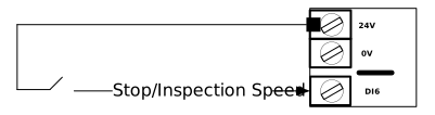
.
| ||
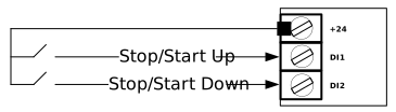 | ||
If the drive trips refer to Troubleshooting. | ||
| ||