Gearless Closed Loop Commissioning
The Elevator Core drive can control Gearless Permanent Magnet Motors in Closed Loop (with Encoder Feedback).
Below are the steps for commissioning the drive for a Gearless Closed Loop application:
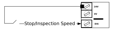
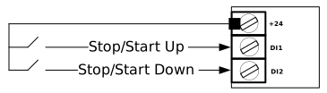
For this guide it is assumed that the electrical wiring follows the default wiring example from below.
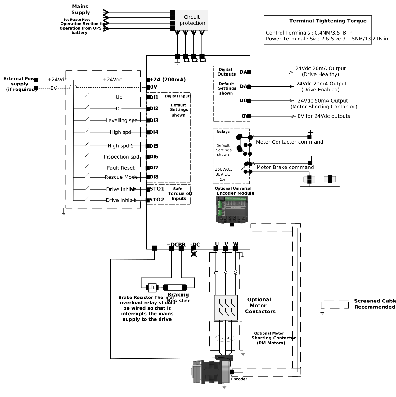
For full detail on electrical installation see the topic electrical installation.
Below are all the checks that must be preformed before applying any power to the drive.
Action/Checks | |
|---|---|
 Do Not Apply Electrical Power Yet! |
|
Check all necessary electrical connections |
|
Check all necessary electrical connections to the Encoder Module |
|
Action/Checks | |
|---|---|
 Apply Electrical Power to the drive |
|
 Check Encoder Module |
|
Step 4 is entering the values from the motor nameplate into the parameters in Group 4.
Warning
This step is mandatory and each parameter needs to have the correct value. If these parameters are not entered or incorrect then the motor could be damaged.
Action | Parameter Change | Additional Information |
|---|---|---|
Select Geared (Induction) motor control |
| This setting supports both IPM and SPM motors |
Enter Motor Rated Current (P4-03) |
| Enter Current value as shown on the motor nameplate (Amps). |
Enter Motor Rated Frequency (P4-04) |
| Enter Frequency value as shown on the motor nameplate (Hz). |
Enter Number of Motor Poles (P4-05) |
| Enter motor pole value as shown on the motor nameplate, if unknown set P4-05 to 0 where the drive will automatically calculate the value providing P4-04 (Motor Rated Frequency) and P4-06 (Motor Rated Speed) have been entered correctly. |
Enter Motor Rated Speed (P4-06) |
| Enter motor rated speed value as shown on the motor nameplate (rpm). The drive display will now show motor speed in estimated rpm. All speed related parameters, such as Minimum and Maximum Speed, run Speeds etc. will also be displayed in rpm. This parameter must be entered in setting P4-05 to 0. If you want the drive to display the speed in Hz leave this parameter at 0. |
Enter the Maximum speed (P8-01) |
| This is the maximum allowable speed. |
During this step we will set up the encoder. This step assumes that the Universal Encoder Module is connected to the drive and correctly wired up. For full details on the mechanical or electrical installation of the Universal Encoder Module refer to the topic - Universal Encoder Module Installation.
For details on the encoder connections see the section Universal Encoder Module - Encoder Connections in this topic.
Action/Check | Parameter Change | Additional Information | ||
|---|---|---|---|---|
Enter Encoder Resolution |
| Refer to the Encoder datasheet or Encoder nameplate | ||
Select Encoder Type |
| P6-04 Setting | Encoder Type | Encoders |
0 (Default) | No Encoder Type Selected | N/A | ||
3 | SinCos (Heidenhain) (With C/D Lines) | ERN 1387 | ||
4 | EnDat 2.1 (With Incremental Signals) | ECN 1313 ECN 113 ECN 413 ECN 1325 ECN 125 ECN 425 | ||
11 | EnDat 2.2 (Without Incremental Signals) | Encoders with no A & B channels | ||
12 | SinCos (Generic) (With C/D Lines) | Non-Heidenhain models | ||
Enable Encoder |
| Setting P6-05 to 1 enables encoder feedback so the drive can be run in closed loop. | ||
Note
Regardless of the encoder type selected the encoder shield must always be connected to the Universal Encoder Module. Failure to do so could result in dropped messages between the encoder and drive causing instability in the motor.
For details on the connection quality between the encoder and the Universal Encoder Module refer to the parameter P6-14 Encoder comms quality.
Below is the connection table for the Universal Encoder Module.
Encoder Type | 24V | 0V | 5V/8V | A+/Sin+ | A-/Sin- | B+/Cos+ | B-/Cos- | C+/CLK+ | C-/CLOCK | D+/DATA+ | D-/DATA | Shield |
|---|---|---|---|---|---|---|---|---|---|---|---|---|
SinCos (ERN1387) | 0V | 5V | A+ | A- | B+ | B- | C+ | C- | D+ | D- | Cable Shield | |
EnDat with Incremental Signals | 0V | 5V | A+ | A- | B+ | B- | CLOCK | /CLOCK | DATA | /DATA | ||
EnDat without Incremental Signals | 0V | 5V | CLOCK | /CLOCK | DATA | /DATA |
A Motor Auto-tune must be carried out in order to measure the motor electrical characteristics, brakes will be applied by the drive (unless controlled by other means) during this test.
Action/Check | Additional Information | ||
|---|---|---|---|
System Check |
NoteFor the motor contactor to close the safety chain will need to be closed. Unless using Macro 9 or Macro 11. | ||
Safety Chain Check |
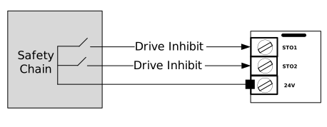 | To start the Auto-tune the Safety Chain inputs must be closed (STO1 & STO2). You are able to pre-load the Auto-tune in P4-08 while the drive shows inhibit (Safety Chain open), so as soon as the Safety Chain close. NoteThe STO input status can be viewed in parameter P0-03 (0 = Open 1 = Closed). | |
Enable Auto-tune Electrical & Encoder Offset measurements |
| Auto-tune Sequence
NoteIf the drive trips on AtF-06 it means that the motor has surface mount magnets, in this case set P4-08 to a 4 for the drive to perform an alternative Encoder offset measurement. | |

Note
The Motor Auto-tune will need to be repeated if the motor, motor cables, motor parameters or drive control mode is changed in P4-01.
Encoder offset value (P6-09) will be wrong if the motor poles (P4-05) has been set incorrectly or if phase orientation is incorrect P11-09 (Output Phase sequence)
This step details the procedure to run the elevator car for the first time.
Action/Check | Guidance | |
|---|---|---|
| Ideally the Lift car should be balanced (i.e. with brakes off, the lift car should not naturally move) and with enough shaft headroom to prevent reaching end stops during initial test travels. | |
| Steps to run the elevator at a reduced speed
NoteIf the drive trips refer to the Troubleshooting topic. | |
| ||
| ||