Group 6 Parameter Descriptions
Group 6.1 - Encoder - Encoder Setup
Parameter Number | Parameter Name | Units | Default | Available Settings | Access | Change During Run | Scaling | Size (Bytes) | CAN Register | CAN Sub Index | Modbus Register |
|---|---|---|---|---|---|---|---|---|---|---|---|
P6-01 | Reserved | - | - | - | - | - | - | - | - | - | - |
P6-02 | Encoder Feedback Direction | N/A | 0: Clockwise Direction | 0: Clockwise Direction 1: Anti-Clockwise Direction | RW | N | N/A | 1 | 2259h | 0 | 602 |
P6-03 | Encoder Pulses Per Revolution | N/A | 2048 | 256 ... 65535 | RW | N | N/A | 2 | 225Ah | 0 | 603 |
P6-04 | Encoder Type | N/A | 0: None | 0 ... 12 | RW | N | N/A | 1 | 225Bh | 0 | 604 |
P6-05 | Encoder Feedback Enable | N/A | 0: Encoder Feedback Disabled | 0: Encoder Feedback Disabled 1: Encoder Feedback Enabled | RW | N | N/A | 1 | 225Ch | 0 | 605 |
Changes the direction of the incremental signals of the encoder feedback signal.
Setting | Function |
|---|---|
0 | A leads B when an Up command is given (Clockwise Direction) |
1 | B leads A when an Up command is given (Anti-Clockwise Direction) |
Sets the number of Pulses Per Revolution for the encoder according the Encoder nameplate/datasheet. This value must be set correctly to guarantee proper operation of the drive when Encoder feedback mode is enabled (P6-05 = 0).
Typically values for Incremental encoders are 512, 1024, 2048, 4096
Note
With an EnDat type encoder the drive reads from the encoder and populates this parameter value automatically.
Set the Encoder type from the table below.
Note
For settings 6,7,9,10 where a single ended encoder is used (e.g. A and B) the unused channels of the encoder module must be connected to 0V.
Setting | Encoder Type |
|---|---|
0 | No encoder type selected |
1 | Incremental TTL- Differential (A,/A,B,/B) |
2 | Incremental HTL-Differential (A,/A,B,/B) |
3 | SinCos with C/D lines |
4 | Endat with Incremental signals |
5 | Incremental TTL- Differential (A,/A,B,/B, Z,/Z) |
6 | Incremental TTL (A,B) |
7 | Incremental TTL (A,B, Z) |
8 | Incremental HTL- Differential (A,/A,B,/B, Z/Z) |
9 | Incremental HTL (A,B) |
10 | Incremental HTL (A,B,Z) |
11 | EnDat without Incremental signals |
Enables or disables encoder feedback. When the encoder is disabled it is referred to as open loop and when the encoder is enabled it is referred to as closed loop.
Setting | Function |
|---|---|
0 | Encoder Feedback Disabled |
1 | Encoder Feedback Enabled |
Note
Even if P6-05 is set to 0 (Encoder Feedback Disabled) encoder feedback can still be monitored (P0-19) providing P6-03 and P6-04 have been set correctly. Encoder feedback Errors are disabled in this mode of operation.
Group 6.2 - Encoder - Encoder Filter Settings
Parameter Number | Parameter Name | Units | Default | Available Settings | Access | Change During Run | Scaling | Size (Bytes) | CAN Register | CAN Sub Index | Modbus Register |
|---|---|---|---|---|---|---|---|---|---|---|---|
P6-06 | Encoder Feedback Filter at Start | ms | 4ms | 1 ... 20ms | RW | Y | 1 = 1ms | 1 | 225Dh | 0 | 606 |
P6-07 | Encoder Feedback Filter Whilst Running | ms | 4ms | 1 ... 20ms | RW | Y | 1 = 1ms | 1 | 225Eh | 0 | 607 |
P6-08 | Encoder Feedback Filter at Stop | ms | 4ms | 1 ... 20ms | RW | Y | 1 = 1ms | 1 | 225Fh | 0 | 608 |
Helps in situations where there is noise on the Incremental encoder cables, and also allows for setting of higher speed loop gains.
Helps in situations where there is noise on the Incremental encoder cables, and also allows for setting of higher speed loop gains.
Helps in situations where there is noise on the Incremental encoder cables, and also allows for setting of higher speed loop gains.
Group 6.3 - Encoder - Encoder Offset and Position
Parameter Number | Parameter Name | Units | Default | Available Settings | Access | Change During Run | Scaling | Size (Bytes) | CAN Register | CAN Sub Index | Modbus Register |
|---|---|---|---|---|---|---|---|---|---|---|---|
P6-09 | Encoder Offset | ° | 0.0° | 0.0 ... 360.0° | RW | N | 1 = 0.1° | 2 | 2260h | 0 | 609 |
P6-10 | Encoder Count/Position | ° | 0.0° | 0.0 ... 359.9° | RO | N | 1 = 0.1° | 2 | 2261h | 0 | 610 |
Populated measurement of the stationary encoder offset measurement when setting the Auto-tune (P4-08) to either setting 2,3,4 or 5.
This value can also be entered manually.
Real-time position of the encoder.
Group 6.4 - Encoder - Speed Error Detection
Parameter Number | Parameter Name | Units | Default | Available Settings | Access | Change During Run | Scaling | Size (Bytes) | CAN Register | CAN Sub Index | Modbus Register |
|---|---|---|---|---|---|---|---|---|---|---|---|
P6-11 | Speed Error Trip Level | % | 10.0% | 0.0 ... 100.0% | RW | Y | 1 = 0.1% | 2 | 2262h | 0 | 611 |
P6-12 | Speed Error Trip Detection Time | sec | 0.5s | 0.0 ... 5.0s | RW | Y | 1 = 0.1s | 1 | 2263h | 0 | 612 |
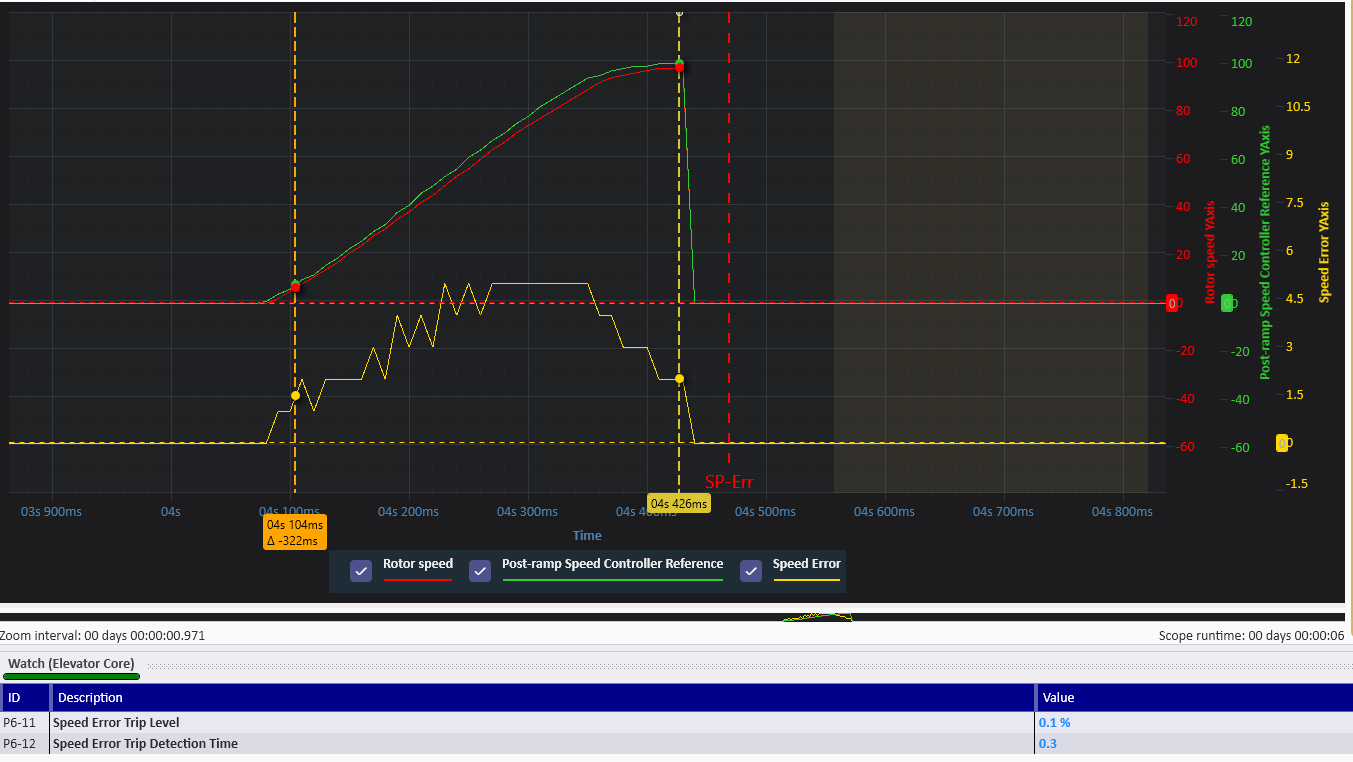
In open or closed loop operation this parameter defines the maximum permissible speed error (as % of the motor rated speed P4-06) between the Post-ramp Speed Controller Reference and the estimated rotor speed (open loop) or encoder feedback speed (closed loop) as calculated by the motor control algorithms. If the speed error exceeds this limit (for the time set in Parameter P6-12 Speed Error Trip Detection Time), the drive will trip Sp-Err.
Example below was on an application with a 1370 rpm rated speed motor, 0.3s detection time and a 0.1% speed error trip level, where 0.1% equates to 1.37rpm (0.001*1370rpm) for 0.3s after which the drive will trip Sp-Err.
In Closed loop operation this parameter defines the maximum permissible speed error between the encoder feedback speed value and the estimated rotor speed calculated by the motor control algorithms. If the speed error exceeds this limit (for the time set in Parameter P6-12 Speed Error Trip Detection Time) , the drive will trip Sp-Err.
Note
The Speed Error Trip does not operate (Function disabled) under the following conditions :
When P6-11 is set to zero
When motor control mode P4-01 is set to 2 (IM VF Mode)
While DC Injection is active.
Used in Conjunction with P6-11 (Speed Error Trip Level) to define to allowed time when the speed is above the value in P6-11 before tripping.
Group 6.5 - Encoder - Encoder Read-Only
Parameter Number | Parameter Name | Units | Default | Available Settings | Access | Change During Run | Scaling | Size (Bytes) | CAN Register | CAN Sub Index | Modbus Register |
|---|---|---|---|---|---|---|---|---|---|---|---|
P6-13 | Encoder Module Error Code | N/A | 0 | 0 ... 255 | RO | N | N/A | 1 | 2264h | 0 | 613 |
P6-14 | Encoder Comms signal Quality | % | 0% | 0.00 ... 100.00% | RO | N | 1 = 0.1% | 2 | 2265h | 0 | 614 |
Displays the Error Codes for the Universal Encoder Module.
Information on the error codes and can be found in the troubleshooting section.
Displays Encoder Communication Signal quality.
If the signal quality is poor this will lead to dropped messages and could lead to poor motor performance.
This parameter is only available for Digital Encoders. When using a TTL or HTL encoder it will always disaply 0.00%.